Table of Contents
Advertisement
Quick Links
OPERATION AND PARTS MANUAL
SERIES
MODEL
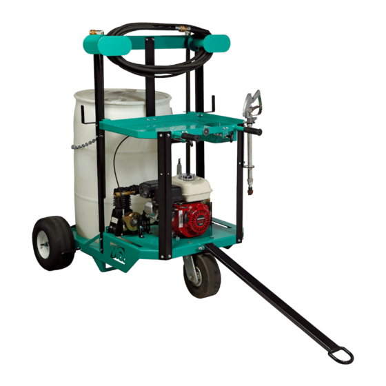
WSC55 SERIES
CHEMICAL SPRAY CART
(HONDA GX160UT2LX2 GASOLINE ENGINE)
Revision #1 (08/30/19)
Original Version
To find the latest revision of this
publication, visit our website at:
www.multiquip.com
THIS MANUAL MUST ACCOMPANY THE EQUIPMENT AT ALL TIMES.
P/N 49356
Advertisement
Table of Contents

Related Manuals for MULTIQUIP Whiteman WSC55 Series

Summary of Contents for MULTIQUIP Whiteman WSC55 Series
- Page 1 SERIES MODEL WSC55 SERIES CHEMICAL SPRAY CART (HONDA GX160UT2LX2 GASOLINE ENGINE) Revision #1 (08/30/19) Original Version To find the latest revision of this publication, visit our website at: www.multiquip.com THIS MANUAL MUST ACCOMPANY THE EQUIPMENT AT ALL TIMES. P/N 49356...
-
Page 2: Fuel And Chemical Exposure Warnings
FUEL AND CHEMICAL EXPOSURE WARNINGS Gasoline engine exhaust and some of its constituents, and some dust created by power sanding, sawing, g r i n d i n g , d r i l l i n g a n d o t h e r construction activities contain chemicals know to cause cancer, birth defects and other reproductive harm. -
Page 3: Silicosis And Respiratory Warnings
SILICOSIS AND RESPIRATORY WARNINGS WARNING WARNING SILICOSIS WARNING RESPIRATORY HAZARDS Grinding/cutting/drilling of masonry, concrete, metal and Grinding/cutting/drilling of masonry, concrete, metal and other materials with silica in their composition may give other materials can generate dust, mists and fumes off dust or mists containing crystalline silica. Silica is a containing chemicals known to cause serious or fatal basic component of sand, quartz, brick clay, granite and injury or illness, such as respiratory disease, cancer,... -
Page 4: Table Of Contents
TABLE OF CONTENTS WSC55 Chemical Spray Cart Component Drawings Nameplate and Decals ........48–49 Fuel and Chemical Exposure Warnings ....2 Cart Assembly ..........50–51 Silicosis and Respiratory Warnings ......3 Compressor Assembly ........52–53 Table of Contents ............. 4 Pump Assembly .......... - Page 5 NOTES WSC55 SERIES CHEMICAL SPRAY CART • OPERATION AND PARTS MANUAL — REV. #1 (08/30/19) — PAGE 5...
-
Page 6: Training Checklist
TRAINING CHECKLIST Training Checklist Description Date Read operation manual completely Machine layout, location of components, checking of engine oil levels Fuel system, refueling procedure Operation of controls (machine not running) Unit startup, engine choke and throttle Spray system operation Compressor operation Unit shutdown Cleanup procedures Unit transport and storage... -
Page 7: Daily Pre-Operation Checklist
DAILY PRE-OPERATION CHECKLIST Daily Pre-Operation Checklist Engine oil level Fuel level Condition of hoses and fi ttings Compressor oil level Tire pressure WSC55 SERIES CHEMICAL SPRAY CART • OPERATION AND PARTS MANUAL — REV. #1 (08/30/19) — PAGE 7... -
Page 8: Safety Information
SAFETY INFORMATION DO NOT operate or service this equipment before reading Potential hazards associated with the operation of this the entire manual. Safety precautions should be followed equipment will be referenced with hazard symbols which at all times while operating this equipment. may appear throughout this manual in conjunction with Failure to read and understand the safety safety messages. - Page 9 SAFETY INFORMATION DECALS Decals associated with the operation of this equipment are defi ned below. DECAL DEFINITION DECAL DEFINITION WARNING NOTICE DO NOT Lift with Barrel/Pails Forklift Left NEVER attempt to lift the spray cart with chemicals loaded on the platform. Left forklift pocket.
- Page 10 SAFETY INFORMATION GENERAL SAFETY NEVER use accessories or attachments that are not recommended by Multiquip for this equipment. Damage CAUTION to the equipment and/or injury to the user may result. NEVER operate this equipment without proper protective ALWAYS know the location of the nearest clothing, shatterproof glasses, respiratory protection, fi...
- Page 11 SAFETY INFORMATION DO NOT allow passengers or riders on the spray cart. WARNING ALWAYS engage the parking brake to prevent rolling If the spray cart is operated indoors, discharge engine while parked. exhaust fumes outdoors. NOTICE NEVER spray corrosive chemicals or water containing toxic substances.
- Page 12 SAFETY INFORMATION ALWAYS use extreme caution when working with WARNING fl ammable liquids. NEVER place hands or fingers inside the engine NEVER fi ll the fuel tank while the engine is running or hot. compartment while the engine is running. ...
- Page 13 SAFETY INFORMATION TOWING SAFETY EMISSIONS INFORMATION CAUTION NOTICE DO NOT tow the spray cart on public roads. The tow The gasoline engine used in this equipment has been hitch is for on-site towing only. designed to reduce harmful levels of carbon monoxide (CO), hydrocarbons (HC) and nitrogen oxides (NOx) ...
-
Page 14: Lifting And Transporting
LIFTING AND TRANSPORTING LIFTING THE SPRAY CART WARNING Using a crane or forklift to lift the spray cart is highly MAKE SURE the rated lifting capacity of the lifting recommended. ALWAYS use extra care when lifting the equipment meets or exceeds the weight of the spray spray cart off the ground. -
Page 15: Specifications
SPECIFICATIONS Table 1. Spray Cart Specifications Model WSC55 WSC55BM WSC55C Weight — lb. (kg) 290 (131) 82 (37) 208 (94) Flow Rate — gpm (liters/min) 9 (34.1) 9 (34.1) Max. Pressure — lb/in² (kPa) 150 (1034) 150 (1034) Hose Length — ft. (m) 50 (15.2) 50 (15.2) Pump Type... -
Page 16: Dimensions
DIMENSIONS Figure 3. WSC55 Spray Cart Dimensions Figure 4. WSC55BM (Barrel Mount) Dimensions Figure 5. WSC55C (Cart Only) Dimensions Table 4. Dimensions Model WSC55 WSC55BM WSC55C (A) Length — in. (cm) 56 (142.2) 26 (66.0) 56 (142.2) (B) Width — in. (cm) 41 (104.1) 21 (53.3) 41 (104.1) -
Page 17: Noise And Vibration Emissions
NOISE AND VIBRATION EMISSIONS Table 5. Noise and Vibration Emissions Model WSC55 WSC55BM Guaranteed ISO 11201:2010 Based Sound Pressure Level at Operator Station in dB(A) Guaranteed ISO 3744:2010 Based ~115 Sound Power Level in dB(A) Whole Body Vibration per ISO 2631- 1:1997+A1:2010 in m/s²... -
Page 18: General Information
GENERAL INFORMATION INTENDED USE Pump and Hoses Operate this equipment only in accordance with the A cast-iron, four-roller pump delivers liquid to the spray manufacturer's instructions. Any deviation from the assembly from the user-supplied drum or buckets. The manufacturer's intended use is strongly discouraged, and pump is equipped with permanently lubricated bearings the risk of such use remains entirely with the user. -
Page 19: Components
COMPONENTS (SPRAY CART) Figure 6. WSC55 Spray Cart Components (Front) Figure 6 and Figure 7 show the location of the spray cart's basic components. Listed below is a brief explanation of each component. 1. Tow Hitch — Allows the spray cart to be transported 8. - Page 20 COMPONENTS (SPRAY CART) Figure 7. WSC55 Spray Cart Components (Rear) 17. Main Hose — A 50-foot (15-meter) hose with 25. Rear Wheel — A single caster wheel provides easy quick-connect fittings for easy coupling with the pump steering of the unit. and spray gun.
- Page 21 COMPONENTS (BARREL MOUNT) Figure 8. WSC55BM Barrel Mount Components The chemical spray system is available as a barrel mount attachment (Model WSC55BM), providing the user with a stationary option. A compressor is not provided with the barrel mount. Figure 8 shows the location of the barrel mount's basic components.
- Page 22 COMPONENTS (COMPRESSOR) Figure 9. Compressor Components An engine-driven, onboard air compressor is provided for clearing liquid from the spray system after use. Figure 9 shows the location of the compressor's basic components. Listed below is a brief explanation of each component. 1.
- Page 23 COMPONENTS (ENGINE) CAUTION DO NOT disable or disconnect the engine ON/OFF switch. It is provided for operator safety. Injury may result if it is disabled, disconnected, or improperly maintained. 5. Recoil Starter — Manual starting mechanism. Slowly pull the starter grip until resistance is felt, then pull briskly and smoothly to start the engine.
-
Page 24: Set-Up
SET-UP INITIAL ASSEMBLY Some assembly is required before the WSC55 can be operated. Refer to the WSC55 Initial Assembly Instructions (P/N 49274) shipped with the unit. Once the initial assembly is complete, proceed with the following set-up instructions. SUPPLY PREPARATION Perform the following procedure to load the chemical platform for use. - Page 25 SET-UP 4. Locate the bung holes on top of the supply container(s). RETURN Break the bung hole cap seals (if necessary) and TUBE SUCTION unscrew the bungs (plugs) to remove. See Figure 14. TUBE DRUM COVER BUNG HOLES LARGER BUNGS HOLE (UNSCREW) SMALLER...
- Page 26 SET-UP SPRAY SYSTEM ASSEMBLY Perform the following procedure to assemble the spray system for use. Refer to Figure 16. RETURN SUCTION HOSE TUBE RETURN SUCTION TUBE HOSE UPPER OUT PORT LOWER OUT PORT RETURN HOSE PUMP IN PORT CLUTCH GUARD MAIN NOT SHOWN HOSE...
-
Page 27: Inspection
INSPECTION BEFORE STARTING 3. Reinsert the dipstick, then remove the dipstick without screwing it in. 1. Read all safety instructions at the beginning of this 4. Check the oil level shown on the dipstick (Figure 18). manual. If the oil level is low, fill to the edge of the oil filler hole 2. - Page 28 INSPECTION SPRAY SYSTEM 5. Inspect the spray gun and spray tips for damage or wear. Replace if necessary. 1. Inspect the pump inlet (IN) and discharge (OUT) lines COMPRESSOR OIL to make sure they are clear. Obstructed lines will prevent self-priming of the pump. See Figure 19. 1.
-
Page 29: Operation
OPERATION INITIAL START-UP It is extremely important that this section is read carefully before attempting to use the spray cart in the field. DO NOT use your spray cart until this section is thoroughly understood. CHOKE LEVER WARNING Failure to understand the operation of the spray cart can result in severe personal injury or damage to the unit. - Page 30 OPERATION 5. Slowly pull the recoil starter grip (Figure 26) until resistance is felt, then pull briskly and smoothly to start the engine. Gently return the starter grip to its original position. Figure 28. Engage Parking Brake Control Levers STARTER GRIP Once the engine has been started, use the control levers located at the rear of the spray cart (Figure 29) to engage Figure 26.
- Page 31 OPERATION Pump NOTICE DO NOT run the pump dry. Excessive heat will damage the pump's rollers and seals. 1. To activate the pump, push the pump control lever forward until it latches in the forward position (Figure 30). The self-priming pump will begin to displace liquid within a few seconds.
- Page 32 OPERATION 5. Slide the pump control lever sideways to unlatch, then pull back on the lever to disengage the pump (Figure 34). COMPRESSOR CONTROL PUMP CONTROL LEVER LEVER Figure 35. Engage Compressor 2. Slide the compressor control lever sideways to unlatch, then pull back on the lever to disengage the Figure 34.
- Page 33 OPERATION 3. Disconnect the suction hose from the quick-connect fitting on the suction tube (Figure 37). Leave the other end of the suction hose connected to the pump. COMPRESSOR QUICK-CONNECT CONTROL FITTING LEVER SUCTION HOSE SUCTION TUBE SUCTION HOSE Figure 38. Engage Compressor COMPRESSOR 6.
- Page 34 OPERATION 7. Slide the compressor control lever sideways to 2. Turn the engine ON/OFF switch to the OFF position unlatch, then pull back on the lever to disengage the (Figure 42). compressor (Figure 40). COMPRESSOR CONTROL LEVER ENGINE SWITCH Figure 42. Engine ON/OFF Switch (OFF) 3.
-
Page 35: Options
OPTIONS SPRAY TIPS NOTICE Four flat, extended-range spray tips are provided with The preceding spray tip specifications are based on the spray assembly. The design of the spray tips reduces spraying water. These specifications will vary when spray drift at lower pressures, and increases spray spraying liquids that are heavier or lighter than water. - Page 36 OPTIONS 4. Make sure your 55-gallon (208-liter) supply drum is located on flat, stable ground. Carefully lift the barrel mount onto the top of the drum (Figure 45). Make sure the unit rests between the bung holes in the drum cover. CAUTION DO NOT attempt to lift the barrel mount by yourself.
- Page 37 OPTIONS 7. Insert the (larger) suction tube and (smaller) return 14. Choose an appropriate spray tip for the desired tube into the top of the drum (Figure 47). If the bung application, and install it onto the end of the spray holes are different sizes, be sure to place the suction gun (Figure 47).
-
Page 38: Maintenance
MAINTENANCE (ENGINE) Use the following table as a general maintenance guideline when servicing your engine. For more detailed engine maintenance information, refer to the engine owner’s manual supplied with your engine. Engine Maintenance Schedule Every 3 Every 6 Every 2 Description First Month Every Year... - Page 39 MAINTENANCE (ENGINE) Engine Oil When performing maintenance on the spray cart or engine, follow all Safety Messages and Rules for Safe Operation NOTICE appearing at the beginning of this manual. ALWAYS drain the engine oil while the oil is warm. ENGINE MAINTENANCE Refer to Figure 49.
- Page 40 MAINTENANCE (ENGINE) Spark Arrester Air Cleaner Refer to Figure 50. 1. Remove and retain the four 5 mm screws securing the muffler protector to the muffler (Figure 51). Remove the muffler protector and set it aside. BLOW COMPRESSED AIR FROM THE INSIDE OUT MUFFLER PROTECTOR...
- Page 41 MAINTENANCE (SPRAY CART) Use the following table as a general maintenance guideline when servicing your spray cart. Spray Cart Maintenance Schedule Every 3 Every Every 60 Months Year or Description (2) Operation Daily Weekly Monthly Days or or 300 1000 200 Hrs.
- Page 42 MAINTENANCE (SPRAY CART) SPRAY CART MAINTENANCE Pump After each use, thoroughly flush the pump with a neutralizing solution for the liquid that was just pumped. Follow with a clean water rinse. LONG-TERM STORAGE When storing the spray cart for more than 30 days, perform the following procedure: „...
-
Page 43: Troubleshooting
TROUBLESHOOTING (ENGINE) Troubleshooting (Engine) Symptom Possible Problem Solution Spark plug bridging? Check gap, insulation or replace spark plug. Carbon deposit on spark plug? Clean or replace spark plug. Short circuit due to defi cient spark plug Check spark plug insulation, replace if worn. insulation? Improper spark plug gap? Set to proper gap. - Page 44 TROUBLESHOOTING (ENGINE) Troubleshooting (Engine) - continued Symptom Possible Problem Solution Air cleaner dirty? Clean or replace air cleaner. Improper level in carburetor? Check fl oat adjustment, rebuild carburetor. Weak in power, compression is proper and does not misfi re. Defective spark plug? Clean or replace spark plug.
- Page 45 TROUBLESHOOTING (SPRAY CART) Troubleshooting (Spray Cart) Symptom Possible Problem Solution Leak in suction line? Check hose and fi ttings for leaks and correct. Inspect hose for obstructions such as debris Obstruction in suction line? or loose inner liner and remove from the line. Suction hose sucked to bottom or side of Cut a notch or “V”...
-
Page 46: Explanation Of Code In Remarks Column
A blank entry generally indicates that the item is not sold assembly/kit that can be purchased, or is not available separately or is not sold by Multiquip. Other entries will for sale through Multiquip. be clarified in the “Remarks” Column. -
Page 47: Suggested Spare Parts
SUGGESTED SPARE PARTS HONDA GX160UT2LX2 GASOLINE ENGINE WSC55 SERIES CHEMICAL SPRAY CART 1 to 3 units 1 to 3 units Qty. Description Qty. Description 3....9807955876 ..SPARK PLUG 2....49273 ....BELT, AX26 2....17210ZE1517 ..ELEMENT, AIR (DUAL) 2....49311 ....BELT, AX37 3....17218ZE1507 ..FILTER, OUTER 2....49308 ....CABLE, CART ENGAGE 1....28462ZH8003 ..ROPE, RECOIL STARTER 1....49290 ....CLUTCH, PUMP MECH. -
Page 48: Nameplate And Decals
NAMEPLATE AND DECALS P/N 49264 P/N 49360 P/N 23808 MODEL SERIAL NO. P/N 49264 P/N 49358 P/N 34629 P/N 49359 P/N 34630 PAGE 48 — WSC55 SERIES CHEMICAL SPRAY CART • OPERATION AND PARTS MANUAL — REV. #1 (08/30/19) - Page 49 NAMEPLATE AND DECALS PART NO. PART NAME QTY. REMARKS 49360 ISO DECAL, DO NOT TOW ON STREET 49264 ISO DECAL, DO NOT LIFT WITH BARREL/PAILS 23805 ISO DECAL, LIFT LOCATION, 1.00” DIA 23808 ISO DECAL, HOT SURFACE HAZARD 49361 ISO DECAL, ENGAGE PARKING BRAKE 23812 ISO DECAL, FUEL GASOLINE 49363...
- Page 50 CART ASSY. PAGE 50 — WSC55 SERIES CHEMICAL SPRAY CART • OPERATION AND PARTS MANUAL — REV. #1 (08/30/19)
- Page 51 CART ASSY. PART NO. PART NAME QTY. REMARKS 49216 WRAP, HOSE 49070 NUT, HFS, 1/4"-20 49223 CRANE HOOK 49242 CHAIN 49215 HOLDER, HOSE 49212 MOUNT, REAR FRAME 49204 FRAME, BASE 23297 MANUAL HOLDER 49213 MOUNT, FRONT FRAME 49214 HOLDER, SPRAY NOZZLE 49048 SCREW, HHFS 1/4"-20 X 3/4"...
-
Page 52: Compressor Assembly
COMPRESSOR ASSY. COMPRESSOR BLUE LOCTITE™ 246 NOTE: APPLY LOCTITE™ 246. PAGE 52 — WSC55 SERIES CHEMICAL SPRAY CART • OPERATION AND PARTS MANUAL — REV. #1 (08/30/19) -
Page 53: Cart Assembly
COMPRESSOR ASSY. PART NO. PART NAME QTY. REMARKS 49255 HOSE ASSY., 3/8" X 28" X 3/8" 49333 FITTING, BRASS 3/4" MNPT-3/8" FNPT 49256 FITTING, BULKHEAD 3/4" NPT 49326 FITTING, 3/4" MNPT FEMALE QUICK 49257 FITTING ADAPTOR 3/8" NPT X 1/4" NPT 32587 FITTING, BRASS TEE 1/4"... -
Page 54: Pump Assembly
PUMP ASSY. WHITE LOCTITE™ 572 NOTE: APPLY LOCTITE™ 572 TO ALL PIPE CONNECTIONS ON ITEMS 1-7 AND 21-25. PAGE 54 — WSC55 SERIES CHEMICAL SPRAY CART • OPERATION AND PARTS MANUAL — REV. #1 (08/30/19) - Page 55 PUMP ASSY. PART NO. PART NAME QTY. REMARKS 49309 REGULATOR, PRESSURE 16585 FITTING, BUSH 1/2" FP-3/4" MP 49327 FITTING, 1/2" MNPT FEMALE QUICK 49333 FITTING, BRASS 3/4" MNPT-3/8" FNPT 49328 FITTING, 3/8" MNPT FEMALE QUICK 49261 PUMP, 4 ROLLER 5/8" SHAFT REWORK 49326 FITTING 3/4"...
-
Page 56: Engine Assembly
ENGINE ASSY. PAGE 56 — WSC55 SERIES CHEMICAL SPRAY CART • OPERATION AND PARTS MANUAL — REV. #1 (08/30/19) - Page 57 ENGINE ASSY. PART NO. PART NAME QTY. REMARKS 49273 BELT, AX26 49354 GUARD, CENTER 49048 SCREW, HHFS 1/4"-20 X 3/4" GRD 5 19266 NUT, BLIND 49311 BELT, AX37 49071 NUT, HFS, 5/16"-18 21906 SCREW, HHFS 5/16"-18 X 1-1/2" GRD 5 49282 ENGINE, HONDA 4.8 HP 49293...
-
Page 58: Wheel Assembly
WHEEL ASSY. PAGE 58 — WSC55 SERIES CHEMICAL SPRAY CART • OPERATION AND PARTS MANUAL — REV. #1 (08/30/19) - Page 59 WHEEL ASSY. PART NO. PART NAME QTY. REMARKS 49229 TIRE, REAR CART 2367 COLLAR, SET .75 X 1.25 X .56 49228 NUT, TOP LOCK 1/2"-13 GRD C/ GRD 5 49275 TIRE, FRONT CART 49277 BUSHINGS, FRONT CASTER 49283 SCREW HHC 1/2"-13 X 6-1/4" 49276 BRACKET, CASTER FRONT 3214...
-
Page 60: Brake Assembly
BRAKE ASSY. PAGE 60 — WSC55 SERIES CHEMICAL SPRAY CART • OPERATION AND PARTS MANUAL — REV. #1 (08/30/19) - Page 61 BRAKE ASSY. PART NO. PART NAME QTY. REMARKS 3910382 BOLT, PLATED SHOULDER, 3/8" X 3/8" 20559-001 SPRING, EXTENSION 3.38 FL. X .71 OD. X .105 49337 SCREW, SHOULDER 3/8" X 3/4", 5/16"-18 SOCKET HEAD 1 49318 CONNECTING BRAKE BAR 35235 WASHER, NYLON, 3/8"...
-
Page 62: Cart Hose Assembly
CART HOSE ASSY. WHITE LOCTITE™ 572 NOTES: APPLY LOCTITE™ #572 PAGE 62 — WSC55 SERIES CHEMICAL SPRAY CART • OPERATION AND PARTS MANUAL — REV. #1 (08/30/19) - Page 63 CART HOSE ASSY. PART NO. PART NAME QTY. REMARKS 49280 SUCTION TUBE ASSEMBLY ......1....INCLUDES ITEMS W/# 49332 FITTING, 90° 3/4" FNPT-3/4" FNPT 49326 FITTING, 3/4" MNPT FEMALE QUICK 49244 TUBE, SUCTION 49307 HOSE, 5' X 3/4" SUCTION ASSEMBLY 49303 HOSE, 50' 3/8" ASSEMBLY 49243 GUN, SPRAY 49331...
-
Page 64: Barrel Mount Assembly
BARREL MOUNT ASSY. WHITE LOCTITE™ 572 NOTE: APPLY LOCTITE™ #572 TO ALL PIPE CONNECTIONS ON ITEMS 3-16. PAGE 64 — WSC55 SERIES CHEMICAL SPRAY CART • OPERATION AND PARTS MANUAL — REV. #1 (08/30/19) - Page 65 BARREL MOUNT ASSY. PART NO. PART NAME QTY. REMARKS 49048 SCREW, HHFS 1/4"-20 X 3/4" GRD 5 49253 GUARD, COUPLING TOP 49310 GAUGE 300PSI LIQUID 8053 FITTING, 90° 1/4" FP-1/4" MP 30384 FITTING, 1/4" MNPT X 1/4" FNPT 49309 REGULATOR, PRESSURE 16585 FITTING, BUSH 1/2"...
-
Page 66: Engine Service Parts
ENGINE SERVICE PARTS PAGE 66 — WSC55 SERIES CHEMICAL SPRAY CART • OPERATION AND PARTS MANUAL — REV. #1 (08/30/19) - Page 67 ENGINE SERVICE PARTS PART NO. PART NAME QTY. REMARKS 17210ZE1517 ELEMENT, AIR CLEANER (DUAL)....1....INCLUDES ITEMS W/# 17218ZE1507 FILTER, OUTER 35120Z0T851 SWITCH ASSY., ENGINE STOP 28461Z4M305 GRIP, RECOIL STARTER 28462ZH8003 ROPE, RECOIL STARTER 9807955876 SPARK PLUG 17620Z4H900 CAP, FUEL WSC55 SERIES CHEMICAL SPRAY CART • OPERATION AND PARTS MANUAL — REV. #1 (08/30/19) — PAGE 67...
- Page 68 © COPYRIGHT 2018, MULTIQUIP INC. Multiquip Inc , the MQ logo and the Whiteman logo are registered trademarks of Multiquip Inc. and may not be used, reproduced, or altered without written permission. All other trademarks are the property of their respective owners and used with permission.