Table of Contents
Advertisement
Quick Links
Advertisement
Table of Contents

Summary of Contents for Fagor WiFi AP-EU
- Page 1 WIFI ACCESS WiFi AP-EU WiFi AP-US POINT Installation manual Ref. 2004...
- Page 2 Fagor Automation does not guarantee the validity of those applications. Therefore, except under the express permission from Fagor Automation, any CNC application that is not described in the documentation must be considered as "impossible". In any case, Fagor Automation shall not be held responsible for any personal injuries or physical All rights reserved.
- Page 3 Obtaining the MAC address of the HBH4 remote terminal ..........26 HBH4 terminal settings ....................27 CNC8065 Communications Test- WiFi access point ............. 29 Hidden Wi-Fi network settings (optional configuration)..........29 Backup and Restore configuration................. 30 WiFi AP-EU WiFi AP-US . 2004 ·3·...
- Page 4 WiFi AP-EU WiFi AP-US . 2004 ·4·...
- Page 5 Declaration of Conformity Declaration of conformity FCC Class B Caution! Any changes or modifications not expressly approved by the party responsible for compliance could void the user's authority to operate this equipment. FCC Radiation Exposure Statement . 2004 ·5·...
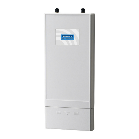
- Page 7 CHARACTERISTICS AND CONNECTION The WiFi AP-EU / WiFi AP-US is a wireless access point that provides wireless network communication coverage for industrial environments. WiFi AP-EU WiFi AP-US . 2004 ·7·...
-
Page 8: Technical Characteristics
Open System, Shared Key, Lagacy 8021X, WPA, WPA2, WPA-PSK (TKIP), WPA2-PSK(AES) Modulation techniques: IEEE 802.11n : OFDM (BPSK, QPSK, 16-QAM, 64-QAM) WiFi AP-EU IEEE 802.11b : DSSS (DBPSK, DQPSK, CCK) WiFi AP-US IEEE 802.11g : OFDM (BPSK, QPSK, 16-QAM, 64-QAM) Channel support: IEEE 802.11b/g/gn:... - Page 9 -89 dBm @ 6 Mbps; -70 dBm @ 54 Mbps 802.11n HT20: -83 dBm @ MCS0/8; -65 dBm @ MCS7/15 802.11n HT40: -80 dBm @ MCS0/8; -62 dBm @ MCS7/15 Dimensions Units: mm WiFi AP-EU WiFi AP-US . 2004 ·9·...
-
Page 10: Product Package
Post mount ring Ferrite core Power cable and 24 V DC power supply The power cord and power supply supplied with the product must be used. Otherwise, the WiFi access point could become damaged. WiFi AP-EU WiFi AP-US . 2004 ·10·... -
Page 11: Hardware Installation
W i F i a cc e s s p o i n t 1.3.2 Hardware installation Ethernet cable connection Remove the lid from the bottom side as shown in the figure. Connect a shielded 6 or 6A STP Ethernet cable to the RJ45 port. WiFi AP-EU WiFi AP-US . 2004 ·11·... - Page 12 Remove the screw from the grounding connection point at the bottom of the WiFi access point. Remove the screw Place the grounding cable and fasten the cable to secure it. Screw the ground cable Slide the lid and press the locking button downward to seal the bottom section. WiFi AP-EU WiFi AP-US . 2004 ·12·...
- Page 13 The WiFi access point must be turned off before connecting the external antennas. The device should not be turned on without having the external antennas connected; otherwise it could cause damage to the unit. WiFi AP-EU WiFi AP-US . 2004...
- Page 14 Incline the other antenna another 45º to the right The polarization of the antennas must be aligned correctly. The maximum signal strength between both bridges is achieved when they use the same polarization. WiFi AP-EU WiFi AP-US . 2004 ·14·...
- Page 15 Do not bend or turn the antennas without first loosening the connector fastener. Otherwise the antennas could become damaged. The installation of the antennas is now complete. WiFi AP-EU WiFi AP-US . 2004 ·15·...
- Page 16 Unlock the post mounting ring using a screwdriver. Flip the WiFi access point. Place the mounting ring through the center hole in the WiFi access point. Securely attach the WiFi access point to the post using the mounting ring. WiFi AP-EU WiFi AP-US . 2004...
-
Page 17: Power Supply Connection
W i F i a cc e s s p o i n t Power supply connection Connect the power cable to the 24 V DC power supply. Connect the Ethernet cable leaving the WiFi access point to the power supply. WiFi AP-EU WiFi AP-US . 2004 ·17·... - Page 18 (between 5.08 and 7.65 centimeters). Tests may be required for the final location depending on its effectiveness in reducing high frequencies. Loop the cable inside the ferrite core. This allows to the core to be fastened in place. WiFi AP-EU WiFi AP-US . 2004...
- Page 19 W i F i a cc e s s p o i n t Close the ferrite core by closing the latches. Connect the Ethernet cable with the attached ferrite core to the "Data in" port of the power supply. DATA IN WiFi AP-EU WiFi AP-US . 2004 ·19·...
- Page 20 Connect the power plug into a power outlet. The WiFi access point will turn on immediately. The device should not be turned on without having the external antennas connected; otherwise it could cause damage to the unit. WiFi AP-EU WiFi AP-US . 2004...
-
Page 21: Basic Diagram
COMMUNICATION SETUP: HBH4 REMOTE TERMINAL - CNC8065 Basic diagram Basic connection diagram for the HBH4 remote terminal for the CNC8065 using a WiFi access point (WiFi AP-EU / WiFi AP-US). CNC8065 HBH4 WiFi (IEC 802.11) remote Standard datas terminal WiFi AP-EU... - Page 22 The following login page will be displayed: • Enter the default username and password to start the session: User: admin Password: password WiFi AP-EU WiFi AP-US The username and password are case-sensitive and the password cannot be longer than 19 characters.
-
Page 23: System Configuration
System / Network Settings Configure the following parameters: • Network Mode: Bridge • Select static IP: Static IP • Change "IP Address" and "Subnet Mask" if required • Press [Apply] to validate the changes. WiFi AP-EU WiFi AP-US . 2004 ·23·... -
Page 24: Wireless Basic Settings
The WiFi network configured for the WiFi access point must be visible when configuring the wireless connection for the HBH4 remote terminal. Selecting the SSID Broadcast: Enabled and press [Apply] to validate the changes. Wireless / Profile Settings Double click on "Profile1". WiFi AP-EU WiFi AP-US . 2004 ·24·... - Page 25 "2.4 Obtaining the MAC address of the HBH4 remote terminal" on page 26. The "MAC Address" option provides greater security settings, but if there are communication issues then any assistance will be more complex. WiFi AP-EU WiFi AP-US . 2004 ·25·...
- Page 26 Access the "System Settings" menu of the HBH4 remote terminal. To do this, press and hold a part on the screen not displaying data. Select the "WiFi" option to retrieve the MAC address for the HBH4 remote terminal. WiFi AP-EU WiFi AP-US . 2004...
- Page 27 • Activate the WiFi and select the option "Configure". • Network property settings. The CNC and the terminal must be connected via a static IP address ("Specify an IP address"). IP Address: 192.168.1.2 Subnet Mask: 255.255.255.0 WiFi AP-EU WiFi AP-US . 2004 ·27·...
- Page 28 • It is possible to see he connection status and select the WiFi access point on the wireless information page. Select the wireless network determined by the WiFi access point and press "Connect". Enter the defined password for the WiFi access point. See "2.3.3 Wireless Settings" on page WiFi AP-EU WiFi AP-US . 2004 ·28·...
- Page 29 The option to hide the WiFi network offers enhanced security settings, but if there are communication issues then any assistance will be more complex. Wireless / Basic Settings Selecting the SSID Broadcast: Disabled and press [Apply] to validate the changes. WiFi AP-EU WiFi AP-US . 2004 ·29·...
-
Page 30: Backup And Restore Configuration
Restore a back-up copy: When clicking "Browse", a file selection menu will appear. Select the desired ".cfg" file and click "Upload" to restore the configuration. The loaded configuration will be applied automatically after restarting. WiFi AP-EU WiFi AP-US . 2004 ·30·... - Page 31 WiFi access point will be restored. Reset button Restarting the device: Click on "Reboot" and press "Yes" when the message appears to commence the restart process. This will take a few minutes. WiFi AP-EU WiFi AP-US . 2004 ·31·...
- Page 32 W i F i a cc e s s p o i nt WiFi AP-EU WiFi AP-US . 2004 ·32·...
- Page 33 W i F i a cc e s s p o i n t . 2004 ·33·...
- Page 34 W i F i a cc e s s p o i nt . 2004 ·34·...
- Page 36 FAGOR AUTOMATION Fagor Automation S. Coop. Bº San Andrés, 19 - Apdo. 144 E-20500 Arrasate-Mondragón, Spain Tel: +34 943 039 800 Fax: +34 943 791 712 E-mail: info@fagorautomation.es www.fagorautomation.com...
Need help?
Do you have a question about the WiFi AP-EU and is the answer not in the manual?
Questions and answers