Table of Contents
Advertisement
Quick Links
Advertisement
Table of Contents

Related Manuals for MME Motorsport GCU7

Summary of Contents for MME Motorsport GCU7
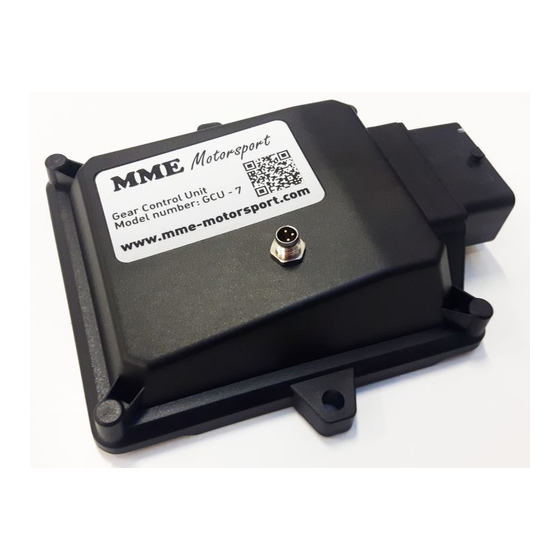
- Page 1 GCU7 Manual 2020-08-26 Gear Control Unit GCU7 Manual...
-
Page 2: Table Of Contents
GCU7 Manual 2020-08-26 Contents Contents ................................ 2 GENERAL OPERATING GUIDE ........................ 3 CONNECTING TO THE GCU ........................3 III. UPGRADING THE FIRMWARE ........................ 5 IV. GAUGES OVERVIEW ..........................6 GENERAL/SENSORS ..........................7 VI. H-PADDLE SHIFTER ACTUATORS SETUP ....................11 VII. H-PADDLE SHIFTER ACTUATORS SETUP - ADVANCED ................ 13 VIII. -
Page 3: General Operating Guide
BUS is already properly terminated. You just need to connect the CAN+ and CAN- to existing line and that’s it. If your car does not have CAN BUS or you’re only connecting the GCU7 on a test bench, you need to insert a jumper in the GCU interface to successfully connect to the GCU. - Page 4 GCU7 Manual 2020-08-26 Remove the two screws: Insert a jumper: Please note: all GCU interfaces come with jumpers installed so if you’re connecting to the existing CAN BUS, you need to remove the jumper.
-
Page 5: Upgrading The Firmware
GCU7 Manual 2020-08-26 III. UPGRADING THE FIRMWARE Please note that firmware and software are published together and they must match. If they do not match, serious problems can occur so always make sure the version of the firmware and software is the... -
Page 6: Gauges Overview
GCU7 Manual 2020-08-26 GAUGES OVERVIEW RPM Gauge shows number of RPM. GEAR POSITION SENSOR - GPS Gear position sensor as the GCU sees it. Green field represents a gear and the range where gear is valid. Gear ranges are only used if GCU is in “Sequential” mode. In H-Paddle Shifter mode, gear position is calculated based on the position of the actuators &... -
Page 7: General/Sensors
Gearbox type: Type: H / Synchro or H / Gearboxes H-Paddle is MME Motorsport actuator assembly that controls 8 valves and shifts any H pattern. For more H-Paddle Shifter options see H-Paddle Shifter actuators. Number of forward gears is in the Number of gears dropdown. - Page 8 GCU7 Manual 2020-08-26 Gear ratios Gear ratio for each gear. GCU will calculate the safe RPM for each gear, according to max engine RPM under the Down tab. See Downshifting for more info. FD is final drive ratio and is currently only used for if speed sensor is enabled. Can be ignored in most of applications.
- Page 9 GCU7 Manual 2020-08-26 Type: CAN Reads the RPM from CAN BUS. CAN Device If CAN is enabled select the ECU you have. If your ECU is not in the list, please contact us with car info and ideally CAN BUS dataset so we include this in the software & firmware.
- Page 10 GCU7 Manual 2020-08-26 Gear calibration In sequential mode, gears must be calibrated. By clicking Calibrate it will walk you through all of the gears and store the values for each gear in the boxes next to the gear. Numbers in boxes are values (0- 1024) where gear is detected.
-
Page 11: H-Paddle Shifter Actuators Setup
GCU7 Manual 2020-08-26 H-PADDLE SHIFTER ACTUATORS SETUP This screen can be opened by clicking the Setup button on GENERAL/SENSORS tab in H-Paddle Shifter actuator region. Before configuring the shift patterns, make sure your Number of gears parameter is correct (GENERAL/SENSORS) For each gear you need to set the position of each actuator. - Page 12 GCU7 Manual 2020-08-26 Horizontal actuator can have 2, 3 or 4 positions, depending on number of gears and shift pattern. Position 1 is fully closed. On power on options allow to set up what actions are taken when you power up the gcu. Vertical actuator: go to position 2 if invalid will move the vertical actuator to position 2 if position on power up is not in the middle (2), completely out (3) or completely in (1).
-
Page 13: H-Paddle Shifter Actuators Setup - Advanced
GCU7 Manual 2020-08-26 VII. H-PADDLE SHIFTER ACTUATORS SETUP - ADVANCED Here you can program the valves for each shift. More info on setting up these parameters coming soon. - Page 14 GCU7 Manual 2020-08-26 VIII. UP Please note: if any parameter is changed, settings must be sent to the GCU (Settings – send to GCU or Send Changed to GCU - F5) in order to take effect. Allow shift N to 1: If disabled, the only way to shift from neutral to 1 , is by hand.
- Page 15 GCU7 Manual 2020-08-26 During shift: Switch UP/DOWN ports (sequential only): if checked, up and down output ports are swapped. Restore power after (deg): This option allows you to return the power before the gear is completely in. If this option is used, it’s very important that the engine ECU takes care of the soft power return (gradually applying the full power).
- Page 16 GCU7 Manual 2020-08-26 Autoshift: Autoshift Mode: Defines the mode used. See below. Activate after (rpm): After which RPM, Autoshift becomes active. RPM must be over this value to start and, when active, If the rpm drop below this rpm, Autoshift is stopped. Please note that this is NOT the rpm where GCU will shift the gear.
- Page 17 GCU7 Manual 2020-08-26 Autoshift Mode: 2 Stage Procedure to start: - Driver must turn the autoshift mode on with the autoshift switch. It’s important that this switch is toggle (fixed position) and not momentary type. LED will turn on. - When RPM is over the Activate after N rpm & While TPS is over %, autoshift mode is activated. LED will be flashing.
-
Page 18: Down
GCU7 Manual 2020-08-26 DOWN Please note: if any parameter is changed, settings must be sent to the GCU (Settings – send to GCU or Send Changed to GCU - F5) in order to take effect. Allow shift 1 to N: If disabled, the only way to shift from 1 to Neutral is by hand. - Page 19 GCU7 Manual 2020-08-26 Before the shift: Disable shift if TPS > %: If throttle is applied (more than Disable shift if TPS >) we don’t want to allow downshift. Typical value: For a dogbox Disable shift if TPS > 20 Min between shifts: the time in milliseconds allowed between shifts.
- Page 20 GCU7 Manual 2020-08-26 Close blip in ms: how many milliseconds does it take to close the blip (ramp). Only used with MME TBC module. Typical value: 0 ms. After throttle blip: Delay before activating valve: how many milliseconds after the throttle blip is closed we activate the downshift actuator.
-
Page 21: Clutch
GCU7 Manual 2020-08-26 CLUTCH Driving bite point: After the shift, this is the position we call bite point and this is the position clutch will go to. Start with the same value as starting bite point (make sure you learn it first). It’s easier to test it when downshifting (blip should be turned off for this setup). - Page 22 GCU7 Manual 2020-08-26 Release duration at 100% throttle: Duration in milliseconds that we release the clutch in (at 100%). Example: if this value is 100ms and you applied only 50% throttle, this duration will be 200ms. Restore throttle at clutch % X in Y ms: after the clutch is returning to zero and it reaches below X %, we restore the throttle back in Y milliseconds.
- Page 23 GCU7 Manual 2020-08-26 - this is it. No other actions needed. You can experiment with few different “feeling points” to get optimal result. Stop bite point when rpm diff <: if at any time rpm difference (while starting) is less than Stop bite point when rpm diff <, clutch returns to zero (in Release duration at 100% throttle time).
- Page 24 GCU7 Manual 2020-08-26 Starting PID: PID parameters for first phase of the car starting off. This is until the car starts to move. Once the car is moving (vehicle speed > 0), PID2 is used. PID controls always checks against the current rpm and the rpm calculated for current gear.
-
Page 25: Misc/Logging
GCU7 Manual 2020-08-26 MISC/LOGGING Please note: if any parameter is changed, settings must be sent to the GCU (Settings – send to GCU or Send Changed to GCU - F5) in order to take effect. LOGGING Leave it Enabled if you want to use GCU logging features. - Page 26 Send to device over CAN: If this is enabled, GCU will output can bus dataset with gear, rpm, button pressed etc. If MME Motorsport DASHBOARD is used, this is the dataset that is broadcasted to the bus: BASE ID: 1983 DLC: 6 BYTE 0: gear number [0-8], 8 being reverse.
-
Page 27: Sequential Gearbox - Quickstart
If you have Engine ECU capable of complete paddle shifting logic, use Ext. Logic. Please note: if you only do the cutting with Engine ECU, you still need the Standalone, because GCU7 will still need to send a signal to cut. ... - Page 28 GCU7 Manual 2020-08-26 Go to UP tab and: Adjust Allow shift from N to 1 and R to N accordingly. Put these to 0: Delay after cut, Keep cut after shift, Don’t cut if TPS <, Actuator preload, Lever return actuator.
-
Page 29: H Pattern Gearbox - Quickstart
If you have Engine ECU capable of complete paddle shifting logic, use Ext. Logic. Please note: if you only do the cutting with Engine ECU, you still need the Standalone, because GCU7 will still need to send a signal to cut. ... - Page 30 GCU7 Manual 2020-08-26 Under DOWN tab: Adjust Allow shift from 1 to N and N to R accordingly. Adjust the Max engine RPM parameter. This is the absolute maximum engine rpm you will able to reach when downshifting.
- Page 31 GCU7 Manual 2020-08-26 Under CLUTCH tab: Leave the Enabled unchecked and skip this chapter if you have a dogbox, otherwise leave it checked. Under Starting off: Set Starting PID to 0.1, 0.1, 0 and PID2 to 0.1, 0.1, 0. Stop bitepoint when rpm diff to 100, Release duration at 100% throttle to 1500.
-
Page 32: Frequently Asked Questions And Troubleshooting
GCU7 Manual 2020-08-26 XIV. FREQUENTLY ASKED QUESTIONS AND TROUBLESHOOTING Can’t connect to the GCU If you see a red DISCONNECTED bar in the bottom it means that either USB CAN interface is not plugged in or you don’t have proper drivers installed. On Windows 7 and newer, drivers are automatically installed once you plugged in, but it could take up to 5 minutes from the to finish loading. - Page 33 GCU7 Manual 2020-08-26 I can shift all gears but N, R and 1 (from N) Make sure you have Neutral and Clutch Sensor properly configured. When shifting up from Neutral or Reverse, check Allow shift from N to 1, Allow shift from R to N and N/R Required from N->1 under UP tab, if they’re properly set.
Need help?
Do you have a question about the GCU7 and is the answer not in the manual?
Questions and answers