Table of Contents
Advertisement
Quick Links
Advertisement
Table of Contents

Subscribe to Our Youtube Channel
Summary of Contents for Emco compact 8
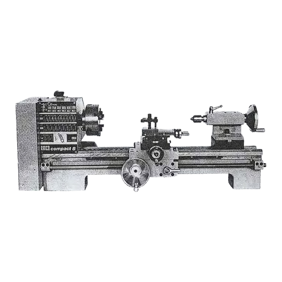
- Page 1 lnstrudiOR book service parts efflCD compact B ENGLISH Edition Ref. Nr. EN 76 04 2 490 Maie1 ELCO MP (PTY) LTD Tel: +27 11 238 7996/7 P.O.Box 5604 A-5400 He Halfway House Fax: +27 86 521 7198 Cell: 082 443 3753 1685 E-Mail: amatt@icon.co.za...
- Page 3 Slides Carriage apron Tailstock Lead screw Drive and electrical equipment Controls Working with the COMPACT 8 Setting the turning tool Manual turning Longitudinal turning with auto-feed - Taper turning using tailstock set-over Taper turning by setting the'top slide - · Turning between centres...
- Page 4 The Standard Equipment includes: Vee Bed Headstock Saddle-,Cross-,Top-SI ides Tailstock Reduction Gear Automatic feed wI th quadrant and 6 change wheels Driving Pin with nut Driver Centre MT3 Centre MT2 Single Tool Holder (Clamp} Electrical Equipment with motor etc. Servicing Tools (Allen key SW 5, ring spanner 10- 13, grease gun} Service Manual...
- Page 7 Slides The strong carriage is made from high-quality cast iron. The siling parts are smooth ground. It fits the Vee on the ped without play. The lower sliding parts can be easily and simply adjusted. Because of the substantial length of the carriage, maxi mum contact is obtained.
- Page 8 Tailstock The tailstock slides on a Vee . a nd can be clamped in any position by means of a heavy screw. The tailstock is made from a vibration-free ribbed iron casting. The slideways are fine ground. The tailstock has a heavy duty barrel with inside taper socket MT2 and a gra- duated scale.
- Page 9 Main switch for motor (forward and reverse) CONTROLS Lever for tensioning and· loosening the Vee belt Long travel handwheel Half-nut lever Cross slide handwheel Top slide handwheel Long travel clamping screw Cross travel clamping screw Tool clamp Tailstock barrel handwheel Tailstock barrel clamping lever Tailstock locking screw ·...
- Page 10 WORKING WITH THE COMPACT 8 Setting the Turning Tool The cutting angle is only correct when the cutting edge is in line with the centre axis of the work piece. The correct height of the tool can be achieved by com...
- Page 12 Screw Cutting (with change wheels) By changing the combination of gear wheels, it is pos sible to cut metric, inch and module threads. For R. H. threads it is necessary for the carriage to travel in the direction of the headstock (normal rota ting direction of the workpiece with closed half-nut) du ring trial runs.
- Page 13 THREAD CUTTING TABLES Metric 0, 5 0,7 0,8 1 1 , 2 5 1 ,5 1,75 2 2 ,5 . .4P .4P 40 4_ 0 H 80 H Zt H 80 H H 80 H 80 H 80 H 3060 40 60 3 560 4060 50 40 5040 7560 7 0 60 80 60 7 5 60 7560 H -- 5() H H j() H H 8() H...
- Page 14 Choosing the correct operating speed Example: Rough turning of a steel shaft 70kp/mm , shaft diameter 45mm, chosen feed 0,09mm/rev. With these values one can find from the diagram the speed and the maximum permissible cutting depth to be used. The cutting. depth is the amount that the cross slide can be fed relative to the suface of shaft. In the diagram for "Steel up to 70kp/mm tensile strength", going along the line "workpiece diameter 45mm"...
- Page 15 LATHE ACCESSORIES Universal Lathe Chuck, 3 or 4 jaw design Using these Universal Chucks, cylindrical or symme trically profiled work pieces (round stock, triangular, square, hexagonal, octagonal or twelve-cornered stock) can be clamped. NOTE: New lathe chucks have very tightly fitting jaws. This is of vital necessity to ensure accurate clamping and a long service life.
- Page 16 Fixed steady The fixed steady serves predominantly as a support for shafts on the free tailstock end. For many operations the tailstock cannot be used as it obstructs the turning tool or the drilling tool, and therefore must be re moved from the machine.
- Page 23 Re-positioning the Vee-Belt Loosen the screw on top of the headstock and open the cover. When re-positioning the belt it is necessary to slacken the idler. That is achieved by moving the lever in the direction of the headstock. Now the belt can be po sitioned on the required stage.
- Page 24 Po sit i o n Grease No . Interval LUBRICATION PLAN • Prior to • starting up • Grease nipple • Feed gear: change gears • Teeth• oil Left hand bearing of leadscrew • • Bed ways: clean and oil Rack: grease over complete length •...
- Page 25 Wiring Diagram "EMCO COMPACT 8" ,· - · - · ·-·-·7 ·-·-·-·-·J L-._. r - ·-·-·-·-· -·-· 1 I .----11------, blue gr ey ------r ..v----,j"------' brown · black @---·j - ·-·-. L_ _____________ j Motor switch Condenser Motor switch diagram...
- Page 26 SERVICETEILE SERVICE PARTS PIECES DE SERVICE...
- Page 27 • 9 · ·10...
- Page 28 Grundausstatt u ng Tools Equipement de base I Pos Ref.No. BENENNUNG DESCRIPTION DESIGNATION 1 zwz 11 0500 Hexagonal key Cl6 coud§e pour 6 pans creux Sechska ntst iftsch lussel Key wrench B2A 000 Ring - Maulschlussel Cltt combin6e plate et oeil Kleinfettpresse Petite pompe A graisse...
- Page 29 15-----f 16�...
- Page 30 Oa-4ahmaschinenbett Lathe bed Banc I Pos DESCRIPTION DESIGNATION Ref.No. BENENNUNG Bett Be d 1 81A 000 Banc nu Zahnstange Rack 2 82A 000 Cr6maillere Lead screw 3 81A 000 Leitspindel Vis-mere Bearing block 4 81A 000 Spindeltrager Paliersupport de vismere (droite) Bearing block 5 82A 000 03011...
- Page 31 121110...
- Page 32 B1A 030 G. Spindelstock Headstock Poup6efixe IPos Ref. N o. BENENNUf\b DESCRIPTION DESIGNATION B1A 030 Spi ndelstock Headstock Carter de poupee fixe B1A 030 Spindel Spindle Broche principale Ke y 3 ZFD 85 8536 A8x5x36 DIN 6885 PaBfeder Clavette B1A 030 Dichtscheibe Gasket Disque d'etancheite...
- Page 33 14 15 22 16 17 I '. · / 3 4 5 1...
- Page 34 Entrainement Antrieb Drive Ref.No. BENENNUNG DESCRIPTION DESIGNATION 81A 060 G. Deckel Cover Couvercle assemble 81A 000 Abdeckblech Covermount T8Ie de couverture 0612 ZSR 12 M6x12 DIN 912 Zylinderschraube Round head screw Vis t@te c· y lindrique ZRG 28 0060 86 DIN 127 Federring Clip Ronde I le grover...
- Page 35 20 1019 9 7 5 4 1516 ·-...
- Page 36 Riemenspanner Tensioning roller Rouleau tendeur Ref.No. BENENNUNG DESCRIPTION DESIGNATION B1A 213 G .. Hebel L ever Levier B1A 000 Hebel Lever Levier ---- - - --- - - - - -- -- - - - - - -- - �--- - ---- ZGF 20 3212 KK 32-12...
- Page 38 E - Ausriistung Electrical equipment Equipement _ '9ectrique Ref.No. BENENNUNG DESCRIPTION DESIGNATION 1 B1A 170 G. E-Gehause E-housing Boitier tlectrique assembl6 2 ZSR 12 0612 M6x12 DIN 912 Z yl i nderschraube Flat head screw Vis t@te cylindrique 3 ZRG 28 0060 B6 DIN 127 Federring...
- Page 39 • -------- 11...
- Page 40 1220 ZMO 95 Motor Motor Moteur I Pos Ref.No. BENENNUNG DESCRIPTION DESIGNATION ZME 95 0001 Stander Stator Stator (inducteur) 2 ZME 95 0002 Laufer Rotor Rotor (induit) 3 ZME 95 0003 PaBfeder Spring Clavette 0004 Ball bearing Kugel lager Roulement billes 5 ZME 95 0005...
- Page 41 ..
- Page 42 Quadrant Riiderschere Lyre Ref. N o. BENENNUNG DESCRIPTION DESIGNATION B1A 000 Schere Quadrant Lyre nue 0630 M6x30 DIN 912 Zylinderschraube Flat head screw Vis tete cylindrique B2A 000 Scheibe Washer Rondelle plate B2A 000 Keilhillse Bush Douille - clavette B2A 000 Scherstift Bushing Goupille de cisaillement...
- Page 43 14 --- 11 - - " 8-----· '...
- Page 44 G. Riidersatz Set of change gears Jeu d'engrenages assembles IPos Ref.No. BENENNUNG DESCRIPTION DESIGNATION • 1 B2A 000 Wechselrad Z = 20 Change gear Engrenage 20 dents 2 B2A 000 Wechsel rad Z = 35 Change gear Engrenage 35 dents 3 B2Z �00 Wechselrad Z = 40 Change gear...
- Page 45 .----- ---- - - 11 ---------- 1 4 ,,,- -- ----- - 20 ,,,-- ------- 5 ,,,,...-------- 6 -- --- 7 - - -- - 25...
- Page 46 Lings- und Querschlitten Saddle and Cross Slide Trainard et chariot transversal IPos Ref.No. BENENNUNG DESCRIPTION DESIGNATION 1 84A 000 Schlitten Carriage 110/1 Trainard nu Querschlitte n 84A 000 Cross-slide-table Transversal nu 3 82A 000 Quermutter Cross-slide-nut Noix du transversal 82A 000 Bettleiste Languette de guidage 84A 000...
- Page 48 G. Obersupport Compound B4A 050 000/1 Chariot superieur BENENNUNG DESCRIPTION DESIGNATION Ref.No. B4A 050 010/1 Obersupport Compound Chariot sui,6rieur nu B2A 050 Oberplatte Swivel base Support-glissillre B2A 050 Einstelleiste Lardon de regtage B2A 050 Klemmring Clamping ring Bague de blocage B2A 050 Skalenring Micrometer collar...
- Page 50 B4A 040 000/1 G. Reitstock Tail stock Poupee mobile assemblee Ref. N o. BENENNUNG DESCRIPTION DESIGNATION 1 B2A 040 Reitstockpinole Tailstock ram Canon 2 B2A 040 Triebschraube Lead screw Broche 3 B2A 040 Bushing Douille d'assemblage Bundbuchse 4 B2A 000 Skalenschild Plate Plaquette graduee...
- Page 51 l'.'lla----------------4 ...,.,__ ___________ 2 G. Lauflilnette Follower rest Lunette a suivre IPos BENENNUNG DESCRIPTION Ref.No. DESIGNATION ..010/1 B4Z 230 Lauflunette Housing Corps B2Z 230 Gleitbacke Touche Nutschraube Screw Boulon en T B2Z 230' Stellschra ube Thumb screw Vis t@te moletee 0800 MS DIN 934 Sechskantmutter...
- Page 52 ®.-. • ----- -- - 6 '" 8--- - -i G. Stehlilnette Steady rest Lunette fixe Ref.No. BENENNUNG DESCRIPTION DESIGNATION 010/1 Stehlunette Housing Corps 1 B42 240 2 B22 230 Gleitbacke Touche Screw 3 B22 230 Nutschraube Boulon en T Thumb screw Vis d!te moletee 4 B22 230...
- Page 53 30 31 ' 22----• · -,' 34 47 39 37...
- Page 54 Tool post grinder Supportschleifapparat Rectifieuse adaptable DESCRIPTION DESIGNATION Ref. N o. BENENNUNG 1 SOB 000 010/1 Kerper Housing Corps Cover Protecteur de courroie 2 SOA 000 020/1 Riemenschutz Bolt Boulon d'articulation du moteur 3 SOA 000 Motorbolzen Riemenscheib e Pulley Poulie du moteur 4 SOA 000 �----------- - - -- -...
- Page 56 Washer Rondelle plate 1050 B10,5 DIN 125 Scheibe Sechskantschraub e 23 ZSR 0508 M5x8 DIN 933 Hexagon head screw Vis t@te hexagonale 24 ZMU 34 0500 MS DIN 934 Mutter Hexagon nut Ecrou hexagonal C4Z 220 EMCO-Folie EMCO Etiquette "EMCO"...
- Page 57 G. Rollkorner Revolving center Pointe tournante I Pos DI N BENENNUNG DESCRIPTION Ref.No. DESIGNATION 1 B22 260 Karper Tapered shank Corps 2 B22 260 Abdeckring Cover Bague de fermeture 3 B22 260 Korner Center Pointe 0800 608 E[8 Ball bearing Rillenkugellager Roulements billes...
Need help?
Do you have a question about the compact 8 and is the answer not in the manual?
Questions and answers