Table of Contents
Advertisement
Quick Links
Advertisement
Table of Contents

Summary of Contents for JetCat EZ-Fuelstation
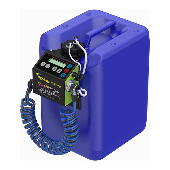
- Page 1 04/2020, V12.01G Instruction Manual EZ-Fuelstation Item. No.: 61105-63...
-
Page 2: Table Of Contents
Contents SAFETY INSTRUCTIONS, MEANING OF THE SYMBOLS ......................3 EZ-FUELSTATION DESCRIPTION ...............................4 MOUNTING THE FUEL STATION ON THE JERRY CAN ........................6 CONNECTIONS..................................7 ..............................7 ONNECTIONS ON THE FUEL STATION ................................8 OCK CONNECTION PRINCIPLE OF OPERATION ...............................9 ............................... 9 NTERNAL CONNECTION DIAGRAM : ..................................... -
Page 3: Safety Instructions, Meaning Of The Symbols
3) S ..........................37 ELECTING MODEL AND START FUELING PROCESS RESETTING THE CONTAINER VOLUME ........................... 38 CHANGING THE MODEL NAME (FILL PROGRAM NAME) ......................39 CHANGING THE CONTAINER NAME ............................40 SERVICE FUNCTIONS ................................41 ..........................41 ESETTING THE VALUES OF THE TATISTICS MENU ............................ -
Page 4: Ez-Fuelstation Description
EZ-Fuelstation description Fully automatic filling or emptying of the model fuel tanks. For this purpose, only a single key is required, the entire refueling/emptying process is then fully automatic! At the end of the refueling process, the pump always switches off automatically. - Page 5 Freely programmable system, with 20 model memories (=filling programs). For each memory, the tank system can be individually programmed/preset e.g.: Model name (plain text) -Type of fuel tank ("normal" tank or bag tank) -Refueling speed (pump capacity) -Drawback volume at the end of the refueling process -Optional "defueling volume"...
-
Page 6: Mounting The Fuel Station On The Jerry Can
Mounting the fuel station on the jerry can Depending on the fuel container used, different jerry can mounting brackets can be attached to the fuel station. The scope of delivery includes interchangeable adapters for fuel jerry cans with nominal diameters of 61 and 71mm. -
Page 7: Connections
Connections Connections on the fuel station Fuel return 4mm hose Fuel inlet 6mm hose Battery input socket, + terminal is on top! FuelDock (see the next page) Expansion socket (e.g. for updates) Fuel return (B), above, black hose (for 6mm hose) Fuel outlet (A), below, blue hose (for 6mm hose) -
Page 8: The Fueldock Connection
The FuelDock connection The optional FuelDock connection, which can be mounted on the right side of the fuel station, has several functions: It serves as a "park" and storage position for the "EZ-Fueler" filling connector. With the "EZ-Fueler" plug- in connector plugged in, the fuel fill hose is connected to outlet A, the fuel flowback line is connected to inlet B. -
Page 9: Principle Of Operation
Principle of operation Internal connection diagram Overflow line from model (input) Flowback line Fuelstation Rücklauf zum Kraftstoffcontainer Überlaufleitung, an den Kraftstoffüberlauf des Modells anschließen. Fuel detector Flow Pump Fuel detector Sensor Fueling line to model (outut) Fuel supply line Kraftstoffbefüllleitung (Ausgang) zum Kraftstoffversorgungsleitung Betankungsanschluß... -
Page 10: "Tank Full" Detection Functionality
"Tank full" detection functionality "Tank full" detection takes place via two different operating principles: A) Fuel returns in the overflow pipe, through the fuel station and then back into the fuel container. As soon as the detector detects fuel in the flowback line, this is a sign that the tank is full. This setting applies when the Stop-Signal parameter is set to 2-line flowback. -
Page 11: Safety Features
Safety features The fuel station has various safety features that try to intercept typical operating errors. In practice, the possible errors that occur are: Overpressure in the tank Forgetting at the beginning of refueling to remove the plug from the tank overflow. Incorrectly refueling a model with bag tank with a program that has set the flowback line as a "tank full"... -
Page 12: Connection Diagram For Model Tank Systems
Connection diagram for model tank systems A) Refueling of a "normal" tank system with flowback line Fuelstation Flowback-line /Rücklauf-Leitung Flowback line / Rücklauf Fuel detector Flow Pump Fuel detector Sensor Fuel supply line Kraftstoffversorgung Fill-line /Befüll-Leitung Fuel container /Kraftstoffreservoir Model to engine /zur Turbine Fueltank(s) -
Page 13: A1) Connection Diagram For Refueling A "Normal" Tank System Without Ez-Fueler Filling Valve
A1) Connection diagram for refueling a "normal" tank system without EZ-Fueler filling valve This results in the following filling cycle: Fuel is first filled into the hopper tank from the blue filling hose. If this is full, the fuel flows into the subsequent tanks until they are also full. At this moment, the fuel then flows into the fuel overflow (or the tank vent hose). -
Page 14: A2) Connection Diagram For Refueling A "Normal" Tank System With The Ez-Fueler Filling Valve
A2) Connection diagram for refueling a "normal" tank system with the EZ-Fueler filling valve Refueling position: The figure above shows the valve position and the resulting connections when the "EZ-Fueler" filling connector is inserted (=filling position). The filling line of the fuel station is connected to the tank filling line. ... - Page 15 Flight position: The figure above shows the valve position and the resulting connections with a disconnected "EZ-Fueler" filling connector (=flight position). Refueling connection actively closed Tank overflow connected to model overflow 15/ 53...
- Page 16 EZ-Fueler features, summary 16/ 53...
-
Page 17: B) Connection Diagram, Refueling With Only One Filling Line (Without Flowback Line)
B) Connection diagram, refueling with only one filling line (without flowback line) B1) Connection diagram for single bag tanks This variant is used for bag tanks. As soon as the tank is full, the pressure in the tank will rise and fuel flow will drop slightly. -
Page 18: B2) Connection Diagram For Multiple Bag Tanks
B2) Connection diagram for multiple bag tanks Fuelstation Flowback line Fuel detector Flow Pump Fuel detector Sensor Fuel supply line Model to engine Fill-line Bladder-tank(s) Fuel container Fueling connector Bladder-tank(s) /Kraftstoff- befüllanschluß This results in the following filling cycle: Fuel is first filled into the bag tank from the blue filling hose. If both bags are full, the pressure in the bags will increase and at the same time the fuel flow will drop slightly. -
Page 19: B3) Refueling Of Single Normal Tanks Without Flowback Line
B3) Refueling of single normal tanks without flowback line This option is suitable for filling single "normal" tanks. Tanks of the same size connected in parallel can also be conditionally filled (if they fill up quickly). Fuelstation Flowback line / Rücklauf Fuel detector Flow Pump... -
Page 20: Control Panel
Control panel Overview of the control keys Change key. To change values/settings, keep this key pressed. Then change the value with the +/- keys Starts the filling process or pumping Fu e l- Sta tio n forwards + key Scroll forward or Fill increase a value On/Off key as... -
Page 21: Commissioning/Switching On
Commissioning/switching on Power supply For power supply, a corresponding battery must be connected to the MPX socket (bottom right). Recommended batteries: 3s/LiPo 2500-5500mAh 4s/LiFePo4 2500-5000mAh The battery type is defined in the System-Settings (also see page: 30) and may need to be adjusted. By default, the system is preset to a 3s LiPo battery. -
Page 22: Operating Concept
Operating concept The system can manage 20 different "models" with associated setting parameters. For each model, the displayed name can be freely defined by the user. On delivery, model numbers 1-3 are already set with predefined settings. It is possible to adjust these preferences at any time according to your own wishes. -
Page 23: Menu Structure
A refueling process can be initiated using the keys explained on page 35. At the end of the refueling process, the display will show e.g.: This display remains until either any key is pressed, or the fuel station shuts itself off after the inactivity time has elapsed. -
Page 24: Run Menu
Run menu The so-called Run menu is used to select the current model/filling program (1-20) and to display the current operating status/program step, etc. If the pump is not running, only the following 3 display options are available: Model name/name of the Status indicator of the two fuel detectors. - Page 25 When the pump is running, a fourth indication (program step display) is also possible: The current program step and a progress bar for this program step are displayed here. As soon as the pump is running, a symbol appears in the upper left corner which indicates the selected filling mode: Explanation of symbols: Symbol...
-
Page 26: Explanation Of The Run Menu Display
Explanation of the Run menu display Status indicator of the two fuel- Model name detectors Bezeichnung des aktuellen Modells Statusanzeige der beiden (=Füllprogramms) Kraftstoffdetektoren Status of fuel detector 1 (fill line) Status of fuel detector 2 (flow back line) Description of symbols : St dTank 2Li ne x x Beschreibung der Symbole No fuel/air... -
Page 27: Fill-Settings Menu
Fill-Settings menu The "Fill-Settings" menu is used to set/specify the program parameters associated with the selected model/filling program. The settings made in this menu are all assigned to the selected (in the RUN menu) model (=filling program)! Parameter Name Options/ Description Value Range Fuel tank type... - Page 28 Parameter Name Options/ Description Value Range The larger this value is set, the more fuel is removed from the bag tank at the end of the filling process. This value influences, so to speak, how "plump" the bag tank should be. If automatic decompression is not desired, this value can be set to zero (0), the function is then deactivated.
- Page 29 Parameter Name Options/ Description Value Range the sensors. Only then does the actual refueling process begin. If this parameter is set to "DISABLED", the initial aspiration is disabled. "DISABLED" ["ENABLED"] If the parameter "tank type" is set to "bladder tank", this parameter is not visible and is always activated internally, since with these tanks the pumping of air into the tank unnecessarily is to be avoided!
-
Page 30: System-Settings Menu
System-Settings menu Parameter Name Options/ Description Value Range Empty-PumpPow 20-100 [50] Pump capacity in % during defueling/reverse pumping. Important: Do not set the pump capacity too high for the reverse operation, otherwise cavitation bubbles may develop on the suction side, making the measurement of the pumped volume inaccurate. - Page 31 Parameter Name Options/ Description Value Range Max Air AspirTime 5-200 [40s] (When refueling bag tanks) Maximum time in seconds to attempt to aspirate air bubbles from the bag tank. If bubble-free fuel returns from the tank within this time, the next step is triggered immediately. Container Volume 0-100 liters Defines the max.
- Page 32 AutoEmptyLines If there is fuel in the filling line, this can be automatically reverse pumped into the fuel container when the fuel station is switched off manually. If activated, the pump is still operated in reverse for a short time after switching off the fuel station (via the "Stop" key) in order to empty the hoses.
- Page 33 Parameter Name Options/ Description Value Range fuel station switches off normally without flushing. The “Flush Filter” process is only suggested by the system if previously a defueling process happened, and effectively a minimum amount of fuel has been aspirated! Burst Protection "DISABLED", Protection system to avoid the bursting of fuel tanks if the "Low sensitivity"...
-
Page 34: Statistics Menu
Statistics menu Parameter Name Description Total Run-Time Total running time of the pump TotalFuel pumped Total conveyed amount No of fills Number of fills No of drains Number of emptying operations LoBatt counts Number of undervoltage trips Scroll between the different parameters with the key. -
Page 35: Key Commands, Filling Functions
Key commands, filling functions Action Key(s) Fill Start automatic filling process, fill tank completely according to the program. Empty Start automatic emptying process, empty tank completely. Deliver a defined volume. The volume defined under "Fill volume" is delivered. Fill Press twice in succession (about 1s in between) Aspirate the defined volume. -
Page 36: Key Commands, Special Functions
Key commands, special functions The fuel station must be switched off! When switching on the fuel station (using the key) additionally press and hold the keys listed in the Stop table. Action Key(s) to additionally press and hold when switching on Changing the model name (fill program name) Resetting the container volume Fill... -
Page 37: Quick Start Guide
Quick Start Guide 1) Selecting a new model and naming it 1) With the fuel station switched on, press the key once briefly to access the Run menu. St op 2) Press and hold the key and choose a free model location 3) Turn off the fuel station (press and hold key for at least 1.5 seconds) St op... -
Page 38: Resetting The Container Volume
Resetting the container volume If the fuel container is full, it may be necessary to reset the volume meter of the container volume to "full". To reset the counter for the "container volume" (=remaining fuel quantity in the fuel container), proceed as follows: First switch off the fuel station! Then:... -
Page 39: Changing The Model Name (Fill Program Name)
Changing the model name (fill program name) To change/set the current model name, proceed as follows: First switch off the fuel station! Then: Press and hold the key and then switch on the fuel station by pressing key again. St op Now the setting function for changing the model name is selected, the display shows e.g.: The modification/editing of the model name displayed in the bottom line must then be carried out as follows:... -
Page 40: Changing The Container Name
Changing the container name Immediately after switching on, the so-called "Container Name" is displayed in the bottom line. This freely definable name should be used to identify the contents of the fuel container (e.g. Jet-A1, smoke oil, 4-stroke fuel etc.). When delivered, the name of the container is "Jet-A1 + 5%Oil". -
Page 41: Service Functions
Service functions Resetting the values of the Statistics menu To reset the statistics values, proceed as follows: First switch off the fuel station! Then: Press and hold the key and then switch on the fuel station by additionally pressing the key. -
Page 42: Calibrating The Flow Meter
Calibrating the flow meter To calibrate the flow meter, either a measuring cup (e.g. 2000-5000ml) with a precise volume scale or a balance (measuring range of at least 3000g) is required. Test setup: Fuelstation Flowback line / Rücklauf Fuel detector Flow Pump Fuel detector... - Page 43 Procedure: The calibration procedure is divided into three steps: Step 1: The target vessel is first "interactively" filled a with certain starting amount. This is to fill the hoses and to get a certain "liquid start level" in Step 1 the measuring vessel (for the directly subsequent calibration for Schritt 1 the reverse operation of the pump).
- Page 44 To select the calibration function of the flow meter, proceed as follows: First switch off the fuel station! Empty Then: Press and hold the key and then switch on the fuel station by additionally pressing the key. St op The display shows: Now release the keys.
- Page 45 If calibration by weight measurement has been selected then the specific weight of the fuel must be entered afterwards, otherwise the following query is skipped: With the keys, the value can be set, to confirm press the key. Table with specific weights of different fuels/media: Specific weight Medium (kg/liter)
- Page 46 Important: Keep the filling line in the measuring cup! As soon as you are ready, press the key. Fill The system now doses forward as long as the key is pressed. Fill If a sufficiently large quantity (at least 500ml!) has been poured in, release the Fill key. To continue press the key.
- Page 47 Step 3: In the following, the pump is operated backwards, i.e. liquid is pumped out of the measuring cup. The user has to let the pump run by pressing a key until a sufficiently large amount has been pumped back (at least 500ml) and stop in time before the target vessel is empty! Important: Keep the filling line close to the bottom of the measuring cup so that liquid can be pumped out;...
- Page 48 From the entries made, the system calculates the calibration factors for forward and reverse operation and displays them for inspection: Press any key to continue. The calibration values can now be saved: To confirm press the key. In this case, the calibration values are saved, and the system then goes straight to normal operation.
-
Page 49: Firmware Update
Then follow/enable the installation steps. After installing the Update Utility program, follow these steps: 1) Connect the JetCat USB interface adapter to the PC and the "Exp." connection on the fuel station. 2) Switch on the fuel station. 3) Make sure the PC has a connection to the Internet! 4) Now start the previously installed program "JetCat Updater-V12"... -
Page 50: Accessories
Accessories Item number Designation Figure 61105-65 EZ-Fueler Jet-A1 61105-66 "Fuel" filling coupling Filling coupling for 2x6mm hose, coding "EZ-Fueler Jet-A1", anthracite/grey anodized) 61105-67 EZ-Fueler smoke 61105-68 Filling coupling for 2x6mm hose, coding "EZ-Fueler Smoke", red anodized) 21105-35 Dual-fueling spiral hose 61105-69 FuelDock 50/ 53... - Page 51 61105-62 Fuel container (DN71), 20l, "short". BxLxH: 280x380x268mm 61105-63 Scope of delivery: 1x EZ-Fuelstation 1x mounting bracket for fuel station (jerry can closure DN61, Ø 61 mm) 1x mounting bracket for fuel station (jerry can closure DN71, Ø 71 mm)
- Page 52 52/ 53...
- Page 53 Ingenieurbüro CAT, M. Zipperer GmbH Wettelbrunner Straße 6 D-79282 Ballrechten-Dottingen Germany Tel: + 49 (0) 76 34-5056-800 Fax: + 49 (0) 76 34-5056-801 Info@cat-ing.de www.jetcat.de 53/ 53...
Need help?
Do you have a question about the EZ-Fuelstation and is the answer not in the manual?
Questions and answers