
Related Manuals for NuFlo EZ-IN Series


Summary of Contents for NuFlo EZ-IN Series
- Page 1 Class I, Group A, B, C, D, Division I. Complies with ASME Standard B31.3 ® EZ-IN Series BF Turbine Flowmeter Installation Manual CERTIFIED NRTL/C...
-
Page 2: Table Of Contents
Table of Contents Introduction .................... 1 Installation ....................4 Precautions ................... 4 Installation Procedure ..............5 Calibration ....................6 Maintenance and Repairs ............... 6 Removing and Inspecting the Meter ..........6 Reassembling the Meter ............... 9 Specifications and Parts Lists ..............11 Warranty—Limitation of Liability ............ - Page 3 ® EZ-IN Series BF Turbine Flowmeter Manual...
-
Page 4: Introduction
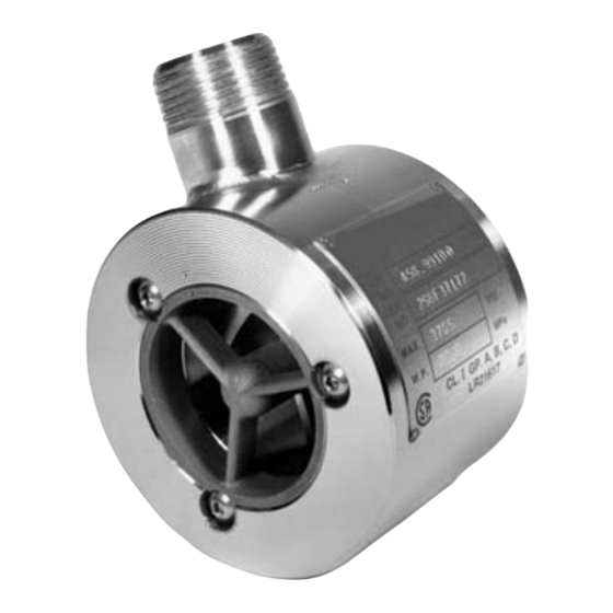
Introduction ® The EZ-IN Series BF (between-flange) Turbine Flowmeter measures flowstream volume in flanged pipelines by transmitting electrical pulses to readout instruments. The flowmeter’s precision turbine has a speed directly proportional to the liquid velocity flowing through the meter. As the turbine rotates, the blades break magnetic lines of force set up by a pickup screwed into the meter body. - Page 5 ® EZ-IN Series BF Turbine Flowmeter Manual Fig. 1—Flowmeter components...
- Page 6 Installation handle Spreader nuts Flange Gasket Body center All-thread bolts, rings nuts, and washers Fig. 2—Assembled flowmeter with optional installation handle...
-
Page 7: Installation
® EZ-IN Series BF Turbine Flowmeter Manual Installation Precautions ® The EZ-IN Series BF Turbine Flowmeter can be installed vertically or horizontally as long as the flow direction appearing on the meter body is the same as the direction of flow in the line. •... -
Page 8: Installation Procedure
Installation Procedure Install a straight section of pipe on either side of the meter. This pipe must be the same size as the meter with a length of at least 10 pipe diameters upstream and 5 pipe diameters downstream. For example, a 6-in. -
Page 9: Calibration
® EZ-IN Series BF Turbine Flowmeter Manual Calibration ® The EZ-IN Series BF Turbine Flowmeter is precalibrated with water at the factory and tagged with the calibration factor in pulses/gal. For maximum accuracy with fluids other than water, calibrate the meter with the actual fluid being measured in the flowline. - Page 10 Flowmeter assembly Magnetic pickup All-thread Gasket stud bolt PART MAX. W.P. CL.I GP.A,B,C,D LR21617 Direction of flow Flange Ring body Conduit thread 4.50 in. PART MAX. W.P. CL.I GP.A,B,C,D LR21617 Fig. 3—Removing and inspecting the meter.
- Page 11 ® EZ-IN Series BF Turbine Flowmeter Manual Lift the meter between the pipeline flanges, using an installation handle if necessary (Fig. 2, Page 3). Remove one of the flowmeter bearing supports (Fig. 1, Page 2). × 1 in. through 1 × 1 in., remove the snap rings. —...
-
Page 12: Reassembling The Meter
Reassembling the Meter Coat the OD of the bearing support with the grease provided in the kit to make subsequent disassembly easier. Caution—Do not lubricate the rotor shaft or bearing. Insert a bearing support in the meter body, making certain its flow arrow and the arrow on the meter are pointing in the same direction. - Page 13 ® EZ-IN Series BF Turbine Flowmeter Manual Return the meter to the line, using the body centering rings to align the meter properly with the interior diameter of the flanges. Carefully align the flange gaskets to help prevent gasket damage. Use the spreader nuts, if necessary, to provide room to lower the meter into the position between the flange gaskets.
-
Page 14: Specifications And Parts Lists
Specifications and Parts Lists ® EZ-IN Series BF Flowmeter Specifications Nom. Calib. Linear Flow Ranges (based on water) ∆p at Max. Flowmeter Max. Output Factor Size Frequency Flow pulses/gal gal/min pulses/sec psi (kPa) (pulses × 1000/m 0.3 to 3 0.068 to 0.68 10 to 100 22,000 (5812) 1,100... - Page 15 ® EZ-IN Series BF Turbine Flowmeter Manual Replacement Rotor and Bearing Support Kits (Precalibrated) Meter Size Standard-Grade Industrial-Grade Linearity ± 1.0% Linearity ± 0.5 % 3/8 × 1 100003521 100003378 3/8 × 2 100079691 101209535 1/2 × 1 100003531 100003379 1/2 ×...
- Page 16 Hardware Kits and Centering Rings (Raised-Face Flanges) Hardware Kits—Price Ref. 800-690 Size (in.) 150 lb 300 lb 600 lb 900 lb 1,500 lb 100014135 100009578 100009578 100079754 100079754 11/2 and 2 100003555 100003556 100003556 100003557 100003557 100003558 100007860 100007860 100003559 100012105 100003560 100003561...
- Page 17 ® EZ-IN Series BF Turbine Flowmeter Manual Hardware Kits (Ring Joint Flanges) Price Ref. No. 800-690 Size (in.) 900 lb 1,500 lb 2,500 lb 1 1/2 and 2 100014145 100080024 100079971 101203294 100079986 100079960 101209541 100080034 100080023 Hardware kit includes bolts, nuts, seal rings, and spreader nuts.
-
Page 18: Warranty-Limitation Of Liability
Warranty—Limitation of Liability WARRANTY - LIMITATION OF LIABILITY: Seller warrants only title to the products, software, supplies and materials and that, except as to software, the same are free from defects in workmanship and materials for a period of one (1) year from the date of delivery. Seller does not warranty that software is free from error or that software will run in an uninterrupted fashion. - Page 19 NuFlo Measurement Systems 14450 John F. Kennedy Blvd. Houston, TX 77032 Phone (800) 654-3760 www.nuflotech.com 100062997NX 11/03 © 2003 NuFlo Technologies, Inc. Printed in USA All Rights Reserved...
Need help?
Do you have a question about the EZ-IN Series and is the answer not in the manual?
Questions and answers