Advertisement
Table of Contents
- 1 Table of Contents
- 2 Safety Rules, Warning
- 3 ECONET ® Scope of Delivery
- 4 ECONET ® Assembly and Installation
- 5 ECONET ® Control and Electrical Installation
- 6 Maintenance Intructions
- 7 Controller Operation
- 8 ECONET ® Functional Description
- 9 Commissioning the Unit
- 10 ECONET ® Communication
- 11 Modbus Addresses
- 12 Display Structure Light
- 13 Safety Instruction
- 14 Spare Parts List
- Download this manual
ECONET
®
LIQUID-COUPLED HEAT EXCHANGER
INSTALLATION & MAINTENANCE MANUAL
FläktGroup
DC_9010GB 20180327_R0
CONTENTS
Safety rules, warning ...............................................................2
scope of delivery .....................................................3
®
Assembly and installation .................................... 7
®
®
Maintenance intructions ........................................................11
Functional description ......................................... 12
®
Controller operation ............................................................... 13
Commissioning the unit........................................................ 23
communication .....................................................24
®
Modbus addresses ................................................................ 25
Display structure light ............................................................27
Safety instruction ................................................................... 28
Spare parts list ....................................................................... 30
Specifications are subject to alteration without notice
Advertisement
Table of Contents

Related Manuals for FläktGroup ECONET

Summary of Contents for FläktGroup ECONET
-
Page 1: Table Of Contents
ECONET ® LIQUID-COUPLED HEAT EXCHANGER INSTALLATION & MAINTENANCE MANUAL CONTENTS Safety rules, warning ...............2 ECONET scope of delivery .............3 ® ECONET Assembly and installation ........7 ® ECONET control and electrical installation .....10 ® Maintenance intructions ............11 ECONET Functional description ......... 12 ®... -
Page 2: Safety Rules, Warning
• Heat recovery liquid is poisonous and harmful and may cause risk of injury if leaking ENVIRONMENTAL REQUIREMENTS FOR STORAGE, TRANSPORTATION AND USE If the Econet unit is not being installed immediately, store the unit in a well-ventilated place away from high tem- peratures, humidity, dust or metal particles. -
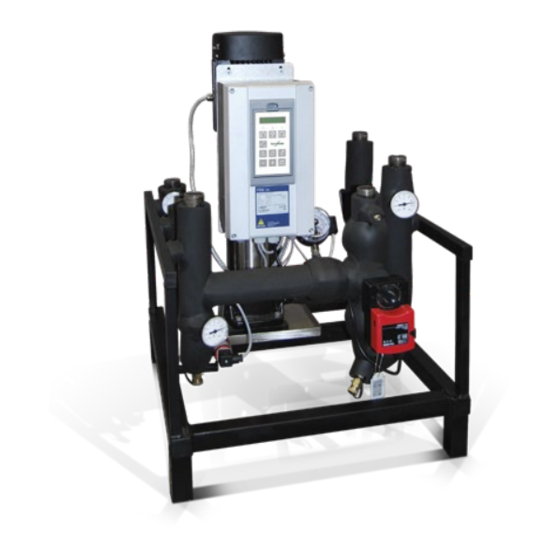
Page 3: Econet ® Scope Of Delivery
The supply air coil and exhaust air coil (11, 12) are mounted in rusting and insulated with Armaflex. the air handling unit. The sensors and components within the pump units (1) are mounted and wired to the ECONET control box. ® Pump unit... - Page 4 VD13803 and VD16022 is required. The supply and exhaust air coils are connected together GP40 by a liquid circuit with the possibility to connect externally supplied energy or heating/cooling. (EQRZ-05 ECONET ® Exchanger Package, see separate manual). GT42 Pump unit:...
- Page 5 Installation & Maintenance Manual LIQUID-COUPLED HEAT EXCHANGER ECONET ® Motor cable STAZ-74 Motor cable GT40 GT40 Exhaust air Frånluft Poistoilma, Abluft EQRZ-05 (Tillbehör) GT41 GT41 Energy GP40 GP40 Heating, Värme ECONET ® Lämmitys, Wärme Cooling, Kyla Jäähdytys, Kälte GT42 GT42...
- Page 6 ® ECONET SCOPE OF DELIVERY ® Controls and components PACKAGING The liquid flow in the ECONET circuit is controlled by the ® Suitable packaging protects the ECONET unit during transport. ® frequency inverter for the pump. The frequency inverter is...
-
Page 7: Econet ® Assembly And Installation
– Filling and air purging of system. – Check the delivered components against the bill of material. – Power supply to the ECONET frequency inverter. ® – The code for the pump unit (STAZ-74-…) can be found on the –... - Page 8 Installation & Maintenance Manual LIQUID-COUPLED HEAT EXCHANGER ECONET ® ECONET ASSEMBLY AND INSTALLATION ® COIL INSTALLATION The coils are installed in the air handling units at the factory. – Installation of pipes between the pump unit, the exhaust air coil and the supply air coil.
- Page 9 OK and recovery. all manual valves are closed. Open and close all valves a couple of times. Start the Econet ® pump. The pump should be run manually via the frequency inverter at maximum 30 Hz.
-
Page 10: Econet ® Control And Electrical Installation
Installation & Maintenance Manual LIQUID-COUPLED HEAT EXCHANGER ECONET ® ECONET CONTROL AND ELECTRICAL INSTALLATION ® POWER SUPPLY CONNECTIONS The inverter must be connected via disconnecting switches. Warning! Main power shall be 3x400 VAC. An electrician shall dimen- Ensure that all wiring is electrically insulated sion the fuses for the pump according to the table below, and and cannot be made “live”... - Page 11 Installation & Maintenance Manual LIQUID-COUPLED HEAT EXCHANGER ECONET ® ECONET CONTROL AND ELECTRICAL INSTALLATION ® CONNECTING THE CONTROL SIGNALS Connect the AHU controller signals to terminals according to the illustration below. The screening of control cables is necessary to comply with the immunity levels given in the EMC Directive.
- Page 12 Installation & Maintenance Manual LIQUID-COUPLED HEAT EXCHANGER ECONET ® ECONET CONTROL AND ELECTRICAL INSTALLATION ® SENSOR CABLE CONNECTIONS Supply Airflow sensor signal The supply airflow signal (GF10) must be connected before commissioning the unit. The signal transducer is part of the air handling unit delivery.
-
Page 13: Maintenance Intructions
Installation & Maintenance Manual LIQUID-COUPLED HEAT EXCHANGER ECONET ® MAINTENANCE INTRUCTIONS GENERAL MAINTENANCE INSTRUCTIONS The ECONET unit does not require regular maintenance, other ® The drip trays for the coils should be cleaned as appropriate. than observing the maintenance instructions provided by the Also ensure thet the water trap is cleaned and filled with water. -
Page 14: Econet ® Functional Description
The specific functions for the AHU must be The pump P40 and frequency inverter FO40 regulate the controlled by a separate controller (not included in the ECONET ® liquid flow to an optimal value for cooling recovery and valve delivery). - Page 15 Installation & Maintenance Manual LIQUID-COUPLED HEAT EXCHANGER ECONET ® OPERATION VIA THE CONTROL PANEL THE DISPLAY GENERAL The display is back lit and consists of 2 rows, each with space The control panel displays the status of the frequency inverter for 16 characters.
- Page 16 When the frequency inverter is set to Local operation, the display will show in area B in the display. In local mode Econet funticons are deactivated. The Econet A-alarm handling is still active where all A-alarms trip the frequency inverter.
- Page 17 Installation & Maintenance Manual LIQUID-COUPLED HEAT EXCHANGER ECONET ® FUNCTION KEYS THE MENU STRUCTURE The function keys operate the menus and are also used for The menu structure consists of 4 levels: programming and read-outs of all the menu settings.
- Page 18 LIQUID-COUPLED HEAT EXCHANGER ECONET ® EcoNet Parameters Settings Description Default EcoNet v5.00 Welcom level OP INFO Operation status of EcoNet unit OP MODE Operation mode HEAT RECOV. 0-100% Heat recovery signal ACT.FLOWSETP Actual flow setpoint LIQUID FLOW Actual liquid flow...
- Page 19 Installation & Maintenance Manual LIQUID-COUPLED HEAT EXCHANGER ECONET ® APPLICATION MANUFACTURER FläktGroup VERSION v5.xx TYPE EcoNet LOG IN Logging in GIVE Give password PASSWRD CHANGE 2000 Change password. C20 shown if logged in PASSW CONFIG Configuration of EcoNet parameters BASIC SETTIN...
- Page 20 Installation & Maintenance Manual LIQUID-COUPLED HEAT EXCHANGER ECONET ® STARTUP Start state setpoint D261 FLOW SETP . 1,5l/s Start flow set point D262 START TIME 3min Start state duration FROST PROT Frost protection GT41 D271 FROST SETP . -3°C Frost protection setpoint...
- Page 21 D535 ALARM DELAY FC SETTINGS Frequency converter settings SPEED D611 MIN SPEED COMM SETTINGS Communication settings ECONETT Econet signals from IO or Modbus D711 START D712 COOLING D713 COOL. REC. D714 HEAT. REC. FLOWS Flow settings from IO or Modbus...
- Page 22 Installation & Maintenance Manual LIQUID-COUPLED HEAT EXCHANGER ECONET ® Motor Freq 50Hz Frequency from motor nameplate Motor Power [Motor] W Power from motor nameplate Motor Curr [Motor] A Current from motor nameplate Motor Speed [Motor] rpm Speed from motor nameplate...
-
Page 23: Commissioning The Unit
This value can be found in the fan module product label. ALTERNATIVE 2 6. Test signals between EcoNet unit and BMS system. Press the + or - key to enter edit mode. Then press the Prev or Connect both functional and component alarms to BMS Next key to move the cursor to the right most position of the system. -
Page 24: Econet ® Communication
• One start bit • Eight data bits D-Sub contact, X2 The D-Sub contact, X2, is used for RS232 communication • One or two stop bits (ECONET use two stop bits) • Even or no parity bit (ECONET use no parity) Name Function Transmit pin. -
Page 25: Modbus Addresses
Actual status cooling start 1x0052 Actual status cooling recovery start 1x0053 Actual status pump feedback 3x0001 Econet start 0= Off, 1 =On Feedback for Holding reg. Actual status 3x0002 Cooling start 0= Off, 1 =On Feedback for Holding reg. Actual status 3x0003 Cooling recovery start 0= Off, 1 =On Feedback for Holding reg. - Page 26 Ice protection controller I Not used 3x0099 Application version number xxx (fac10) Not used 4x0001 Econet start 0= Off, 1 =On 4x0002 Cooling start 0= Off, 1 =On 4x0003 Cooling recovery start 0= Off, 1 =On 4x0004 Heating recovery input signal...
-
Page 27: Display Structure Light
Installation & Maintenance Manual LIQUID-COUPLED HEAT EXCHANGER ECONET ® FläktGroup DC_9010GB 20180327_R0 Specifications are subject to alteration without notice... -
Page 28: Safety Instruction
Installation & Maintenance Manual LIQUID-COUPLED HEAT EXCHANGER ECONET ® SAFETY INSTRUCTION INSTRUCTION MANUAL RESIDUAL CURRENT DEVICE (RCD) COMPATIBILITY Read this instruction manual before using the Variable Speed This product cause a DC current in the protective conductor. Drive, VSD. Where a residual current device (RCD) is used for protection in... - Page 29 Installation & Maintenance Manual LIQUID-COUPLED HEAT EXCHANGER ECONET ® IT MAINS SUPPLY DC-LINK RESIDUAL VOLTAGE The variable speed drives can be modified for an IT mains supply, (non-earthed neutral), please contact your supplier for Warning! details. After switching off the mains supply, dangerous HEAT WARNING voltage can still be present in the VSD.
-
Page 30: Spare Parts List
Installation & Maintenance Manual LIQUID-COUPLED HEAT EXCHANGER ECONET ® SPARE PARTS LIST List of items that can be provided as spare parts. Ordering code: STAZ-74-bbb-c-d-e-f-g-h-i-j-k bbb = eQ-size PART MAKER TYPE NOTE Bypass-valve Johnsson controls 005, 008, 009 =>BG 005 => V6 1801 –...
Need help?
Do you have a question about the ECONET and is the answer not in the manual?
Questions and answers