Advertisement
860582188
Issue 1, November 2014
www.commscope.com
SYSTIMAX
General
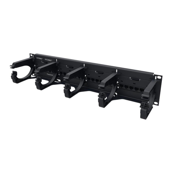
The SYSTIMAX
PATCHMAX
(3U) version. These panels are approved components for use in SYSTIMAX PowerSUM and GigaSPEED XL
systems.
SYSTIMAX PATCHMAX panel systems are designed for premises high speed data and voice networks. Wire
terminations can be performed from the front or rear of the frame. These panels can be used for EIA-T568A or
EIA-T568B wiring applications.
The panels use snap-in distribution modules, each with six modular jacks. Panel kits are available unpopulated
for use with separately ordered modules.
Ordering information is listed below:
Material ID
Part No.
760062356
PM-GS3-24
w/Termination Mgt.
760062364
PM-GS3-48
w/Termination Mgt.
760001669
PM-GS3-2U
760001677
PM-GS3-3U
760205260
PM-PS-24
760205278
PM-PS-48
760205286
PM-PS-2U Panel Kit
760205294
PM-PS-3U Panel Kit
How to Contact Us
To find out more about CommScope
For technical assistance:
-
Within the United States, contact your local account representative or technical support at
1-800-344-0223. Outside the United States, contact your local account representative or
PartnerPRO
-
Within the United States, report any missing/damaged parts or any other issues to CommScope
Customer Claims at 1-866-539-2795 or email to claims@commscope.com. Outside the United
States, contact your local account representative or PartnerPRO Network Partner.
®
PATCHMAX
Modular Panel Instructions
GS3 and PowerSUM modular panels are available in a 24-port (2U) and 48-port
PATCHMAX GS3 Cat 6 U/UTP copper patch panel, 24-port, equipped with
termination manager
PATCHMAX GS3 Cat 6 U/UTP copper patch panel, 48-port, equipped with
termination manager
PATCHMAX GS3 24-port panel kit (without modules)
PATCHMAX GS3 48-port panel kit (without modules)
PATCHMAX PowerSUM copper patch panel, 24-port (2U), equipped with
termination manager
PATCHMAX PowerSUM copper patch panel, 48-port (3U), equipped with
termination manager
PATCHMAX PowerSUM 2U panel kit (without modules)
PATCHMAX PowerSUM 3U panel kit (without modules)
®
products, visit us on the web at
™
Network Partner.
© 2014 CommScope, Inc. All rights reserved
®
GS3 and PowerSUM
Description
www.commscope.com/
For RoHS Inquiries:
CommScope Inc.
Corke Abbey, Bray
Co. Dublin, Ireland
Attn: Legal Department
®
Page 1 of 8
Advertisement
Table of Contents

Summary of Contents for Systimax PATCHMAX GS3
- Page 1 GS3 and PowerSUM modular panels are available in a 24-port (2U) and 48-port ® (3U) version. These panels are approved components for use in SYSTIMAX PowerSUM and GigaSPEED XL systems. SYSTIMAX PATCHMAX panel systems are designed for premises high speed data and voice networks. Wire terminations can be performed from the front or rear of the frame.
-
Page 2: Tools Required
860582188 www.commscope.com Instruction Sheet Tools Required Phillips head screwdriver Cable jacket scoring tool D-914 punch tool with M110 blade Parts List Verify parts against the parts list below: Quantity Description 24-Port Panel 48-Port Panel 2U Panel Kit 3U Panel Kit –... -
Page 3: Warning! Important Safety Instructions
Separately Orderable Parts Modules for the PM-GS3 and PM-PS panel kits must be ordered separately and are listed below: Material ID Product Number Description PM-GS3-DM PATCHMAX GS3 Category 6 U/UTP distribution module 760065763 PowerSUM PATCHMAX Category 5e U/UTP distribution module 760205302... - Page 4 860582188 www.commscope.com Instruction Sheet Step 1 – Mount Panel to Rack Mounting screw (4 places) 1. Using four screws (included), attach panel to 19-inch rack. 2. Install retainer bar to rear of panel. Step 2 – Populate Panel with Distribution Modules (For Panel Kits Only) Note: Distribution modules are ordered separately.
- Page 5 www.commscope.com 860582188 Instruction Sheet Step 3 – Cable Modules Front View Rotate and remove module Release snap Insert module posts into slots Attach designation label Attach retainer Replace module Route cables through panel opening Attach retainer Terminate cables Secure cables to retainer bar Route cables Rear View...
- Page 6 860582188 www.commscope.com Instruction Sheet Front Punch-Down Procedure 1. Release snap to disengage module from panel. 2. Rotate module downward and remove from panel. 3. Route an adequate length of cable through the module openings as shown. 4. Insert module posts into panel mounting slots and snap module into position. Note: The module comes with a T568B wiring designation label installed.
- Page 7 www.commscope.com 860582188 Instruction Sheet Termination Manager Instructions The termination managers provide pair positioning, control, and strain relief features to the rear termination area of the panel. See Figure 1. Instructions for using the termination manager are listed below. Feed Pairs into Termination Manager (Figure 2) 1.
- Page 8 860582188 Instruction Sheet Snap Termination Manager onto Rear Housing Pairs (Figure 4) folded back 7. Snap assembled termination manager onto rear housing with pair colors in proper position. Push on using the termination manager, not by pushing with the cable. (Ensure that both snaps on manager fully seat into rear housing.) 8.
Need help?
Do you have a question about the PATCHMAX GS3 and is the answer not in the manual?
Questions and answers