Table of Contents
Advertisement
Quick Links
INSTALLATION & OPERATION MANUAL
FOR
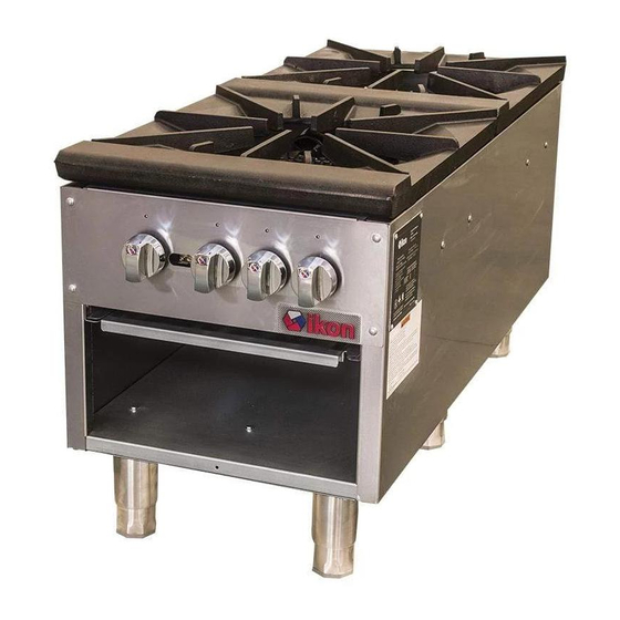
STOCKPOT RANGE
MODEL: ISP18
MODEL: ISP182
WARNING: IMPROPER INSTALLATION, ADJUSTMENT, ALTERATION, SERVICE OR MAINTENANCE
CAN CAUSE PROPERTY DAMAGE, INJURY OR DEATH. READ THE INSTALLATION, OPERATING AND
MAINTENANCE INSTRUCTIONS THOROUGHLY BEFORE INSTALLING OR SERVICING THIS EQUIPMENT.
1
Advertisement
Table of Contents

Related Manuals for Ikon ISP18


Summary of Contents for Ikon ISP18
- Page 1 INSTALLATION & OPERATION MANUAL STOCKPOT RANGE MODEL: ISP18 MODEL: ISP182 WARNING: IMPROPER INSTALLATION, ADJUSTMENT, ALTERATION, SERVICE OR MAINTENANCE CAN CAUSE PROPERTY DAMAGE, INJURY OR DEATH. READ THE INSTALLATION, OPERATING AND MAINTENANCE INSTRUCTIONS THOROUGHLY BEFORE INSTALLING OR SERVICING THIS EQUIPMENT.
-
Page 2: For Your Safety
IMPORT ANT FOR YOUR SAFETY THIS MANUAL HAS BEEN PREPARED FOR PE RSONNEL QUALIFIED TO INSTALL GAS EQUIPMENT, WHO SHOULD PERFORM THE INITIAL FIELD START- UP AND ADJUSTMENTS OF THE EQ UIPMENT COVE RED BY THIS MANUAL. POST IN A PROMINENT LOCATION THE INSTRUCTIONS TO BE FOLLOWED IN THE EVE NT THE SMELL OF GAS IS DETECTED. -
Page 3: Installation
INSTALLATION, OPERATION AND CARE OF STOCKPOT RANGE GENERAL Stockpot ranges are designed for commercial use only and feature fast, efficient gas heat. Each burner is controlled by an adjustable gas valve. Heavy-duty, cast iron top grate(s) are easily removed for cleaning when cool. A grease drawer is provided to collect fat run-off;... -
Page 4: Installation Codes And Standards
LOCATION The installation location must be kept free and clear of combustibles. Do not obstruct the flow of combustion and ventilation air. DO NOT install the stockpot adjacent to open burners or fryers. Sufficient air should be allowed to enter the room to compensate for the amount of air removed by any ventilating system and for combustion of the gas burners. -
Page 5: Leg Installation
LEG INSTALLATION The stockpot range is shipped without the legs attached. The stockpot range must not be operated without the legs attached to the unit. 1. Remove cast iron grate and burners from chassis. 2. Turn chassis upside down and locate the leg plate to alight the four screw holes (Fig. 1). 3. -
Page 6: Ventilation Hood
LEG ORIENTATION LEGS LEGS GAS PRESSURE REGULATOR INSTALLATION Gas regulator pressure is preset at 5” Water Column (W.C.) f or natural gas, and 10” W.C. for propane gas. Minor adjustments may be required based on site specific gas pressure . Install the regulator as close to the stockpot on the gas supply line as possible. -
Page 7: Gas Connection
GAS CONNECTION T he data pl ate on the rear of the stock pot indicates the type of g as your u nit is equipped to burn. DO NOT connect to any other gas type. NOTICE Gas supply connections and any pipe joint compound must be resistant to the action of propane gases. -
Page 8: Lighting Instructions
PILOT PILOT VALVE SCREW INNER BURNER OUTER BURNER Fig. 6 Fig. 5 LIGHTING INSTRUCTIONS 1. Turn all burner valves to OFF position and wait 5 minutes. 2. Turn gas shutoff valve ON. 3. Light standing pilot with a lit taper (see Fig 6) . Adjust pilot to ¼” high f lame, if necessary, b y turning pilot valve adjust in g screw (see F ig . -
Page 9: Maintenance
MAINTENANCE The stockpot range and its parts are hot. Use care when operating, cleaning or servicing the stockpot range. LUBRICATION Al l valves must be checked and lubricated periodically . At the first sign of sticking , valves should be lubricated by a trained technician using high temperature grease. Check with your service agency for details. - Page 10 Conversion to LP gas orifice Take out the grate on the top. You can see the orifice is on front of the burner as below Fig.7 show. Fig. 7 2. As Fig. 8 show, screw out the Nat. gas orifice[#32(φ3.0mm)] counter-clockwise, then screw in the LP gas orifice[#43(φ2.3mm)] clockwise.
- Page 11 When service is needed, contact a IKON Authorized Service Agency, or your dealer. To avoid confusion, always refer to the model number, serial number, and...
- Page 12 Limited Warranty IKON warrants to the original purchaser of new equipment that said equipment, when installed in accordance with our instructions within North America and subjected to normal use, is free from defects in material or workmanship for a period of 1 year. The labor warranty is one year from original installation or 18 months from actual factory shipment date whichever date occurs first.
Need help?
Do you have a question about the ISP18 and is the answer not in the manual?
Questions and answers