Advertisement
Available languages
Available languages
Quick Links
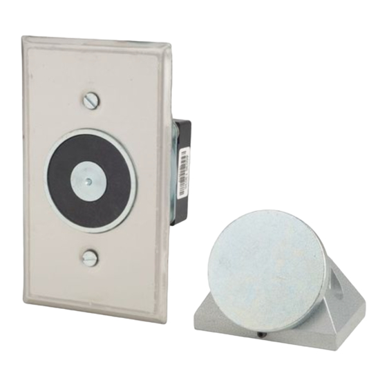
Description
The 1509 Series are flush mount door holders for use with single
doors. The units are UL and cUL Listed and FM approved
Installation
Install and wire in accordance with applicable codes, standards,
such as NFPA publications 70 (National Electrical Code), 72 (Na-
tional Fire Alarm Code), and 80 (Standard for Fire Doors and Fire
Windows), and/or other regulations applicable to the country
and locality of installation and in accordance with authorities
having jurisdiction.
Y
Door
Door jamb
Figure 1. Locating the Door Holder
1.
Using Figure 1 and Table 2, locate the intersection of
Dimension X and Dimension Y. Dimension Z is shown at the
intersection in the gray area.
NOTE: If dimension X or Y is not shown on the chart,
extrapolate Dimension Z. (i.e., if X=7, and Y=28,
Z = (27-5/8 - ((27-5/8 - 27-1/4)/2) => Z = 27-9/16"
2.
Install a single gang outlet box (not supplied) on the
horizontal center line and 5" from the top of the door.
NOTE: The outlet box must be able to withstand a maximum
holding force of 50 pounds.
If X and Y intersect in the blank area in Table 2, DO NOT
install the outlet box. The contact plate and electromagnet
cannot be aligned with these dimensions.
28
30
2 26 (660)
28 (711)
4 26 (660)
28 (711)
6 25 5/8 (651)
27 5/8 (702)
8 25 1/4 (641)
27 1/4 (692)
10 24 5/8 (625)
26 3/4 (679)
12 23 3/4 (603)
25 7/8 (657)
14 23 3/4 (603)
25 (635)
16 21 3/4 (552)
24 (610)
18 20 (508)
22 1/2 (572)
20 18 1/4 (463)
21 (533)
22
18 3/4 (476)
24
26
Do not install outlet box if
Dimensions X and Y intersect in this blank area.
28
30
The armature and electromagnet cannot be aligned.
32
CHESHIRE, CT 203-699-3300 CUST. SERV. FAX 203-699-3365 TECH SERV. FAX 203-699-3078
Installation Instructions for Flush Wall Mount Electromagnetic Door
center
line
Outlet box
Wall line
X
Table 2. Dimension chart (in inches)
32
34
29 7/8 (759)
32 (813)
34 (864)
29 7/8 (759)
32 (813)
34 (864)
29 5/8 (752)
31 3/4 (806)
33 3/4 (857)
29 1/4 (743)
31 3/8 (797)
33 1/2 (851)
28 3/4 (730)
30 7/8 (784)
33 (838)
28 (711)
30 1/8 (765)
32 1/4 (819)
27 1/4 (692)
29 3/8 (746)
31 1/2 (800)
26 1/4 (667)
28 1/2 (724)
30 3/4 (781)
25 (635)
27 3/8 (695)
29 3/4 (756)
23 1/2 (597)
26 (660)
28 1/2 (724)
21 5/8 (549)
24 3/8 (619)
27 (686)
22 1/2 (572)
25 1/2 (648)
Holders Catalog Series 1509
Cat. No.
1509-E1
1509-E5
1509-AQN5
Electromagnet Assembly and Cover Mounting
To prevent electrical shock, ensure power is discon-
nected.
1.
Refer to Figure 2. Pull field wiring through conduit into the
single gang outlet box.
Z
2.
Establish earth-ground continuity in accordance with
applicable codes, standards and authorities having
jurisdiction. A green insulated lead wire is provided on -
AQN5 models for this purpose.
3
For -E1 and -E5 models, connect the field power wiring to the
electromagnet assembly wiring leads.
For -AQN5 models, refer to Figure 3 and connect as
instructed below:
a.
120V AC operation. Connect power field wiring to
terminals marked "120V AC" and "COM."
b.
24V AC/DC operation. Connect power field wiring to
terminals marked "24V AC/DC" and "COM."
4.
Secure the electromagnet bracket assembly to the outlet box
using two #6-32 x 1/2" screws provided (Figure 2).
5.
Mount the cover to the electromagnetic bracket assembly
and secure with the two #6-32 x 3/8" screws provided
(Figure 2).
NOTE: The combined projection of the electromagnet
assembly and armature assembly is 1 27/32".
Armature Assembly Mounting
NOTE: Armature assembly must be mounted vertically
(Figure 4) to obtain correct alignment with the
electromagnet.
Y = Dimension of door width
36
38
40
36 (914)
38 (965)
36 (914)
38 (965)
35 3/4 (908)
37 3/4 (959)
35 1/2 (902)
37 3/8 (949)
35 (889)
37 (940)
34 3/8 (873)
36 3/8 (924)
33 3/4 (857)
35 7/8 (911)
33 (838)
35 1/8 (892)
32 (813)
34 1/4 (870)
30 7/8 (784)
33 1/8 (841)
29 3/8 (746)
31 3/4 (806)
28 1/8 (714)
30 5/8 (778)
26 1/4 (667)
29 (737)
Table 1. Specifications
Volts
12V DC
12V AC 60 Hz
24V AC 60 Hz
24V DC
120V AC 60 Hz
WARNING
42
44
40 (1016)
42 (1067)
43 7/8 (1114) 45 5/8 (1159)
40 (1016)
42 (1067)
43 7/8 (1114) 45 5/8 (1159)
39 3/4 (1010) 41 3/4 (1060) 43 5/8 (1108) 45 3/8 (1153)
39 1/2 (1003) 41 1/2 (1054) 43 3/8 (1102) 45 1/4 (1149)
39 1/8 (994)
41 1/8 (1045) 43 (1092)
38 1/2 (978)
40 5/8 (1032) 42 1/2 (1080) 44 3/8 (1127)
38 (965)
40 (1016)
42 (1067)
37 1/4 (946)
39 3/8 (1000) 41 3/8 (1051) 43 3/8 (1102)
36 1/2 (927)
38 5/8 (981)
40 5/8 (1032) 42 1/2 (1080)
35 3/8 (899)
37 5/8 (956)
39 5/8 (1006) 41 5/8 (1057)
34 1/8 (867)
36 1/2 (927)
38 5/8 (981)
33 1/8 (841)
35 5/8 (905)
37 7/8 (962)
31 5/8 (803)
34 1/4 (870)
36 1/2 (927)
29 3/4 (756)
32 1/2 (826)
34 7/8 (886)
27 3/4 (705)
30 5/8 (778)
33 (838)
31 3/8 (797)
P/N 3100539 ISSUE 1 © 2003
A m p s
0.170
0.150
0.015
0.015
0.015
46
48
44 7/8 (1140)
43 7/8 (1114)
40 3/4 (1035)
40 (1016)
38 5/8 (981)
37 1/8 (943)
35 3/8 (899)
33 7/8 (860)
501-152800-0-01
Advertisement

Summary of Contents for Edwards Signaling 1509 Series
- Page 1 Holders Catalog Series 1509 Table 1. Specifications Description Cat. No. Volts A m p s The 1509 Series are flush mount door holders for use with single 1509-E1 12V DC 0.170 doors. The units are UL and cUL Listed and FM approved 1509-E5 12V AC 60 Hz 0.150...
- Page 2 Electromagnet Single gang Cover Cover bracket VIEW outlet box (side view) (front view) assembly (by others) (side view) FRONT 4 5/8 po VIEW 120V AC 24V AC/ (117 mm) (2) 6-32 x (2) 6-32 x 1/2 po (13 mm) 3/8 po (9.5 mm) 2 3/4 po screws (supplied) screws (supplied)
- Page 3 Instructions pour l’installation des dispositifs électromagnétiques de retenue de porte à montage mural encastré, séries 1509 Tableau 1. Caractéristiques électriques Description de cat. Ampères Volts Les appareils de la série 1509 sont des dispositifs à montage 1509-E1 12V c.c. 0,170 mural encastrés, conçus pour retenir une seule porte.
- Page 4 Vue de Boîte de sortie Support-couvercle de format Électroaimant Couvercle Couvercle dessus simple (non fournie) (vue de côté) (vue de côté) (vue de face) Vue de 4 5/8 po face (117 mm) 120V AC 24V AC/ (2) vis de 6-32 x (2) vis de 6-32 x 2 3/4 po 1/2 po (13 mm)
Need help?
Do you have a question about the 1509 Series and is the answer not in the manual?
Questions and answers