Table of Contents
Advertisement
Quick Links
Advertisement
Table of Contents

Subscribe to Our Youtube Channel
Summary of Contents for Data Signs VMS II Series
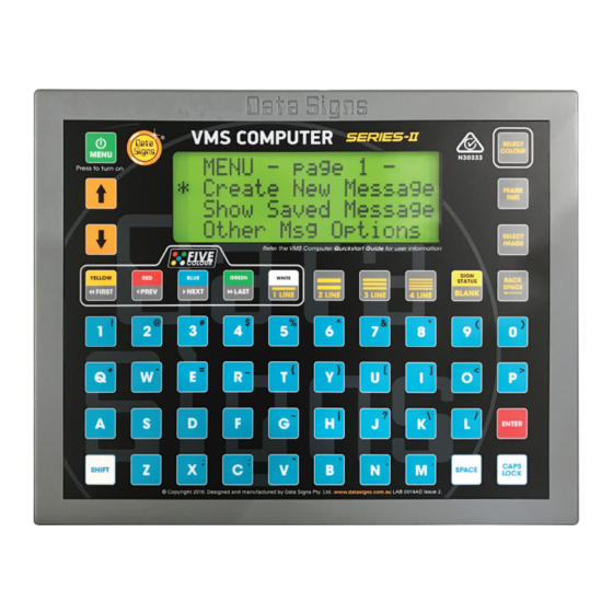
- Page 1 VMS Computer Advanced Features • DataSigns...
-
Page 2: Table Of Contents
VMS Computer This manual covers the Advance features of the VMS Product. For further Training for this product contact Data Signs on 1300 785 850. This User Manual applies to Controllers operating on firmware xx.xx.xx or later. THE VARIABLE MESSAGE SIGN SHOULD ONLY BE OPERATED BY QUALIFIED TRAFFIC MANAGERS. -
Page 3: Advanced Vms Computer Functions
Advanced VMS Computer Functions To setup the Radar Options on a Sign fitted with an optional Radar Gun supplied by Data Signs, complete the following steps, as a guide. Note: Make sure that you have the correct VMS Password set on the VMS COMPUTER before trying to update the Sign. - Page 4 2. On the next screen select ‘Show Speed First’ as the 1st display option and push the ENTER button. • Because ‘Show Speed first’ was selected, the Sign will show the detected speed on the Sign first. • If ‘Radar Msg first’ was selected, the Sign would first display either the RadarHi / RadarLo message on the Sign when a speed was detected by the Radar Gun.
- Page 5 5. Next, set the Minimum speed and push the button to continue. This is the speed above which the Sign will display the speeds detected by the Radar Gun. For example, if the speed zone where the Sign is positioned is 60 km/h, you may only want to show detected speeds on the Sign greater than 25 km/h.
- Page 6 7. On the next screen set the Maximum speed and push the ENTER button to continue. Any speeds detected that are higher than the Maximum speed you set will not be shown by the Sign. For example 100, this is to prevent encouraging drivers to ‘drag race’ in the streets and use the Sign as a speed readout.
-
Page 7: Set Radarhi Speed Or Radarlo Speed Messages
Set RadarHi Speed or RadarLo Speed Messages From the Radar Options main MENU, you can also set the Radar Hi and Radar Lo messages. These messages are displayed on the Sign when you selected ‘Show Radar Msg…’ in the Radar Setup. For example, you have selected to ‘Show Speed first’... -
Page 8: Set Radar Gun Sensitivity
Set Radar Gun Sensitivity It may be useful to set the Sensitivity where the radar unit is picking up false readings from trees for example (so, too sensitive) or where the radar unit is not picking up cars from far enough away (not sensitive enough). -
Page 9: Tma Mode (Truck Mounted Attenuator)
TMA Mode (Truck Mounted Attenuator) TMA Mode is used when the DataSign-VMS is mounted on the back of a TMA. Set the SIGN STATUS button from the ‘VMS Computer Optns’ menu, and go to ‘Status Btn Func’ sub-menu item. The sticker as shown on the left can be placed over the SIGN STATUS button to show the operator that this button is now used to enter TMA Mode. -
Page 10: Timer Functions
Timer Functions Timer functions will allow you to display the current date & time on the Sign, or to set a timer to count up or to count down like a stop-watch. This function is very useful for Public Event, Like Marathons etc. To display the current date &... - Page 11 To set and display the count up options on the Sign complete the following steps from the ‘Timer Functions’ menu option. keys, select ‘Set to Count Up’ option and press the 1. Navigating via the button. 2. In the ‘Set To Count Up’ screen use the keys on the VMS COMPUTER to enter the time to count up to. For example, enter 00:00:10.
- Page 12 5. To resume the counter, press the button. The counter will now resume on the Sign. Press the button again and the counter will Pause again, and so on. C O U N T O P T I O N S : ( R E ) S T A R T C O U N T E R P A U S E...
-
Page 13: Time Of Day Offset Adjustment
Time of Day Offset Adjustment This advanced function is to offset the GPS time in the Sign from GMT (Greenwich Mean Time) to set the actual time for your region. It is generally only needed if the SIM card is not fitted and no connection back to WebVMS server is available. -
Page 14: Sign Status
Sign Status This will show the Status of the sign, including: 1. Serial Number, WW,Y,NN, Week of year, Year letter (A=2017, B=2018 ect), Unit number that was manufactured that week 2. VMS Sign Controller Firmware version xx.xx.xx. (The VMS Computer serial number is displayed on start-up) 3. -
Page 15: Disclaimer
Suggestions & Improvements Data Signs develops its products with the end users in mind. As such, we are always open to suggestions for product improvement. Contact Data Signs, Head Office in Australia at: dsinfo@datasigns.com.au Disclaimer The information contained in this document is proprietary information of Data Signs Pty Ltd unless otherwise indicated.
Need help?
Do you have a question about the VMS II Series and is the answer not in the manual?
Questions and answers