Table of Contents
Advertisement
Quick Links
Advertisement
Table of Contents

Summary of Contents for Kimo GP 500 Series
- Page 1 GP 500 - 1 : 0 – 2500 Pa GP 500 - 2 : 0 – 10 000 Pa...
-
Page 3: Table Of Contents
Table of contents 1. Introduction............................5 1.1. General presentation........................5 1.2. Technical specifications.......................6 1.2.1 General technical specifications....................6 1.2.2 Technical specifications in measurement and pressure generation........6 1.3. Electrical connections........................7 2. Use of the GP 500..........................8 2.1. Turn on the device........................8 2.2. Configure the device before a measurement or a generation.............8 2.2.1 Activate or deactivate the automatic autozero..............8 2.2.2 Set the integration.........................8 2.2.3 Select the unit........................8... -
Page 5: Introduction
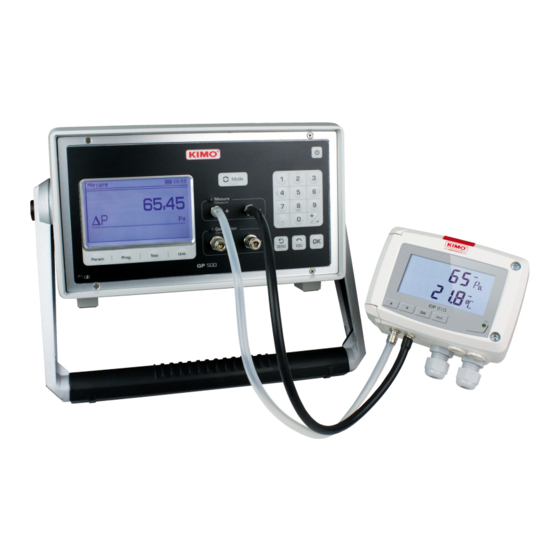
1.1. General presentation The pressure generator allows the adjustment and the calibration of the measuring instruments in laboratory or on site. There are two versions : GP500 0-2500 Pa : from -2500 to +2500 Pa ● GP500 0-10 000 Pa : from -10 000 to 10 000 Pa ●... -
Page 6: Technical Specifications
1.2. Technical specifications 1.2.1 General technical specifications Display Backlight graphic LCD Size : 85 x 51 mm Resolution : 240 x 180 pixels Connection measuring ports Ribbed connectors for tubes Ø 6 x 2 mm Connection generation ports Quick-coupling connectors DN2.7 Power supply 230 Vac ±10 % / 50-60 Hz or on battery Consumption... -
Page 7: Electrical Connections
GP 500 0-10 000 Pa : Measuring range From -10 000 to +10 000 Pa Accuracy* in measuring ±0.15 % of the reading +6 Pa Generation range From -10 000 to -50 Pa and from +50 P to +10 000 Pa Accuracy* in generation From -10 000 to -1000 Pa : 10 Pa From -1000 to +1000 Pa : 1 Pa... -
Page 8: Use Of The Gp 500
2.1. Turn on the device To turn on the GP500 : Connect the GP500. ➢ It is not compulsory to connect the GP500. Its internal battery has 8 hours of autonomy. However, in case of extended use, it is recommended to connect it on the mains power source. Press on “On/OFF”... -
Page 9: Visualize The Points
2.3.1 Visualize the points Go to the line “Show items” then press on OK. ➢ The device displays the points which have been generated and compared with the standard. 2.3.2 Perform an internal generation (correction) The internal correction allows to launch a series of setpoints defined by the GP500. The device generates 21 setpoints. Connect the “Generation”... -
Page 10: Launch A Measurement Program
Press on “Prog” . ➢ The screen displays the different programs. The device proposes to execute or to modify a program. With the high and low arrows go to the desired program then with the left and right arrows select “Change”. ➢... -
Page 11: Generate A Pressure
2.6. Generate a pressure In addition to “Measurement program” part, it is possible to generate the desired pressure in a really simple manner. Press on “Mode” to be in “Generation” mode. ➢ The green led located next to “Generation” lights up. Enter the desired pressure with the numeric keypad then press on OK to validate. -
Page 12: Perform A Leak Test
The GP 500 allows to test an existing aeraulic network and thus verify if leaks are present in this network. Press on “Test”. ➢ The “Leak test” screen displays. This screen allows to configure the test then to start it. Go to the line “Order”... -
Page 13: Device Settings And Information
4.1. Device settings It is possible to set the following parameters of the GP500 : The auto shut-off ; • The blacklight ; • The contrast ; • The key beep ; • The date. • Press on “Param.” ➢ Go to the line “Settings”... -
Page 14: Device Information
4.2. Device information Press on “Param.” ➢ Go to the line “Informations” then press on OK. ➢ The screen displays the different information concerning the GP500 : Software version. Ex : v1.000 (b0274) ● Serial number. Ex : 5F.14.01.16777215 ● Calibration date. -
Page 15: Use Of The Software
The GP500 is delivered with a LGP500 software allowing to perform the following actions : Configure the different programs ● Perform a calibration ● Configure the integration in pressure ● Update the device ● 5.1. Minimum configuration required For the good functioning of the software, the following configuration is strongly recommended : Minimum configuration : Windows, XP, VISTA, 7 ●... -
Page 16: Configure The Programs
5.4. Configure the programs The “Programs” tab lists the programs saved in the GP500 as well as the stages linked to the programs. It also allows to modify them. In the “Programs” part : Click on the desired program. ➢ Enter the stage duration in second in the column “Period (s)”. -
Page 17: Create A Correction Table
To add a stage to a program : Click on the desired program. ➢ Click on in the “Steps” part. ➢ If a program contains 20 stages, the software will indicate that the maximum number of stages has been reached. 5.5. -
Page 18: Modify The Integration Of The Pressure Measurement
5.6. Modify the integration of the pressure measurement The GP500 pressure measurement element is very sensitive and very reactive to the pressure changes. During the measurements on an unstable aeraulic network, the pressure measurement becomes illegible. The integration coefficient (from 0 to 9) then allows to smooth the pressure measurement in order to avoid the untimely variations and allow the exploitation of a more stable measurement. -
Page 19: Modify The Software Language
Click on “Browse”. ➢ Go in the file where is situated the .bin update file. ➢ Click on “Send”. ➢ The following window opens : The GP500 restarts and displays the message “Programming flash” during the updating. At the end of the updating, the GP500 turns off and the software indicates that the updating has succeeded. Click on OK.
Need help?
Do you have a question about the GP 500 Series and is the answer not in the manual?
Questions and answers