Table of Contents
Advertisement
Quick Links
Advertisement
Table of Contents

Summary of Contents for TheSunPays BALI48
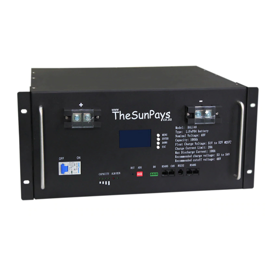
- Page 1 Lithium-ion Battery Pack Model: BALI48 User manual Version: 1.4...
-
Page 2: Safety Precautions
1. Safety precautions Please strictly comply with all warnings and operating instructions in this manual. Keep this manual in a safe place and read the following instructions carefully before installing the unit. Do not operate this unit before carefully having read through all safety information and operating instructions. -
Page 3: While Charging
Disconnect the power supply in operation: While operating the power supply, you must first switch off power supply. Use of power operation is not allowed. DC short circuit dangerous: Power system provides Direct Current regulated power supply. Remember, Direct Current short circuited could cause fatal damage to the equipment. 1-2 While charging CAUTION The temperature range over which the battery can be charged is 0°C to 45°C. -
Page 4: Table Of Contents
2.Table of Contents 1. Safety precautions ....................... 2 1-1 When in use ......................2 1-2 While charging ......................3 1-3 When discharging the battery ..................3 2.Table of Contents ......................4 3. Parameters of battery ....................7 3-1 Parameters of battery pack ..................7 3.2 Technical parameters of Battery Management System (BMS) ........ - Page 5 6. BMS operations ......................40 6-2. Buzzer operation (optional) ..................41 6-3. Reset key function ....................41 7. Troubleshooting ......................42 8. Storage and maintenance .................... 42 8-1. Storage ......................... 42 8-2. Maintenance ......................42 9. Product responsibilities and consulting ............... 44...
-
Page 7: Parameters Of Battery
3. Parameters of battery 3-1 Parameters of battery pack Model of battery pack BALI48 Nominal voltage Rated capacity Above 100AH Rated reserved energy 4800WH Maximum charging current 1C(100A) Total charging cut-off voltage 54.75V Floating charge voltage 52.5±0.5V Cut-off voltage of charging cell 3.65V... -
Page 8: Technical Parameters Of Battery Management System (Bms)
Weight 43kg Gravimetric specific energy 112WH/Kg Compound mode 15 Cells in series 3.2 Technical parameters of Battery Management System (BMS) Function name Item list Set value Setting range Alarm value of cell overvoltage Overvoltage alarm voltage 3,600±20mV 4,500mV 1,000mV Cell voltage alarm Undervoltage alarm voltage... - Page 9 1. When the cell voltage is lower than the recovery point, automatically recover charging. Cell Overvoltage recovery 2. When the cell voltage is lower than the protection point and the capacity is ≤95% (regularly overvoltage conditions protection charging conditions: Charging once per day), recover charging.
- Page 10 Recovery value of total voltage overvoltage Overvoltage protection voltage 55.5±0.3V Recovery value of total Battery voltage undervoltage overvoltage 50.2±0.3V protection Overvoltage recovery Protection value of total voltage voltage overvoltage 1. When the total voltage is lower than the recovery point, automatically recover charging. Overvoltage recovery 2.
- Page 11 Undervoltage recovery The valid charging current is detected and the conditions voltage is higher than the recovery point. Low temperature alarm High temperature alarm of 55±3℃ value of battery cell to battery cell 90℃ -40℃ Battery cell Low temperature alarm of temperature battery cell High temperature alarm...
- Page 12 Protection value of charging low temperature 0±3℃ Charging low temperature recovery Recovery value of charging high temperature Recovery value of discharging high 60±3℃ temperature Discharging high temperature protection 90℃ No discharging Recovery value of due to discharging low temperature of temperature the battery cell Protection value of...
- Page 13 -15±3℃ Discharging low Recovery value of temperature recovery discharging high temperature Alarm value of low ambient temperature High ambient temperature alarm 65±3℃ 90℃ Ambient -40℃ temperature alarm Low ambient temperature -20±3℃ alarm Alarm value of high ambient temperature Recovery value of MOS high temperature Mos-Over-Temperature Alarm(℃)...
- Page 14 protection Recovery value of charging low temperature 85±3℃ Mos-Over-Temperature Protection Release(℃) Protection value of charging high temperature Recovery value of high ambient temperature High ambient temperature protection 70±3℃ 90℃ Recovery value of low ambient temperature 50±3℃ High ambient temperature Protection value of high recovery ambient temperature -40℃...
- Page 15 Alarm value of charging Charging current overcurrent Charging protection protection current 130±2A 100A It may be set to be 0, i.e. Charging current close the charging current limiting function Charging limiting current limiting function. Protection value of discharging overcurrent Discharging overcurrent alarm Discharging alarm current 125±2A...
- Page 16 Continuous overcurrent 3 times locking 100 times Charging equilibrium of Cut-in conditions: State of valid charging current battery cell 3,000mV Equilibrium cut-in voltage 3,450mV 4,500 mV Voltage difference value after equilibrium Voltage difference of equilibrium cut-in 30mV 100mV 10mV Voltage difference after equilibrium Voltage difference value of 20mV...
- Page 17 -20℃ 0 ℃ Prohibition value of Equilibrium low equilibrium high temperature prohibition temperature Static equilibrium of Cut-in conditions: All non-discharging states battery cell Estimate based on the voltage of the battery cell After overvoltage protection, when the rest capacity of the battery is reduced to 95% below or meets the regular charging conditions (charging once per day), recover charging if the voltage is lower than the overvoltage protection setting point.
- Page 18 data record and ≥ 1000 records alarm history Display of SOC Measure and Module level: ≤ 0.5V of accuracy Cell level: ≤ 0.05V of accuracy monitor accurancy Measure and monitor the current of battery module Accuracy: ≤ 5% Measure and monitor the temperature of battery...
-
Page 19: Dry Contact Description
3-3 Dry contact description Functions and pin description: • 1, 2 Start on alarm • 3, 4 Start on battery power is low... -
Page 20: Basic Block Diagram
4. Basic block diagram There are Battery cells and BMS board inside, before connecting the terminal, please read the • diagram, and make sure the output is not short or other abnormal connection Fig. 1 Battery Block Diagram 5. Installation and operation 5-1. -
Page 21: Panel View
NOTE: Before installation, please inspect the unit. Be sure that nothing inside the package was damaged during transportation. Do not turn on the unit, but notify the carrier and dealer immediately if there is any damage or parts missing. Please keep the original package in a safe place for future use. 5-2. - Page 22 Dry contact 1,2 alarm 3,4 low power...
-
Page 23: Single Battery Installation
5-3. Single battery installation Installation and wiring must be performed in accordance with the local electricity laws/regulations and the following instructions must be executed by professional personnel. 1) Make sure the mains wire and breakers in the building follow the standard rated capacity of the battery to avoid any hazards of electric shock or fire. -
Page 24: Software Installation
5-4. Software installation For optional computer system protection, install battery monitoring software to fully configure battery shutdown and other setting values. 5-5. Installation of battery in parallel 5-6 Installation precautions 1) Prior to installation, unpack to check the quantity of the parts and battery appearance; 2) Install the hanger and handle and measure the battery voltage with a multimeter. - Page 25 such as the torque wrench must not contact the positive and negative terminals of the battery at the same time to avoid a battery short-circuit; 5) Before the battery is connected with the externally connected equipment, disconnect the equipment and check whether the connecting polarity of the battery and total voltage are correct. Connect the battery anode with the equipment anode and battery cathode with the equipment cathode and fix the connecting line;...
-
Page 26: Operation Instruction For Installation
Installation of standard cabinet (rack): Install the matching hanger for the battery pack and fix them in the standard cabinet. The tray protection is added for the battery box. Installation of wall-mounted box: Prior to installation, please ensure that the wall complies with the wall-mounted requirements;... - Page 27 Shutdown In the non-standby state of BMS, press the key 3S to shutdown; Reset In the non-standby state of BMS, press the key for 10S, until all LEDs light up for reset. 3) Installation of the lithium battery, wiring and startup. Disconnect the battery pack and switch it off to put it in a standby state.
- Page 28 Lithium Copper core Copper Remarks battery cable pigtail 48V50Ah 16mm ~25mm 16-8/25-8 M8 copper pigtail is used for 48V50Ah sing pack of battery binding post 48V100Ah 16mm ~25mm 16-10/25-10 48V100Ah M10 copper pigtail used 48V100Ah sing pack of battery binding post Introduction to operation steps in detail according to the required capacity: •...
- Page 29 Step 6: Draw out two wires from the anode and cathode of a battery pack at the top or in the middle respectively as the main connecting line of the battery pack in parallel, which is connected with the switching mode power supply or UPS. Step 7: Press the RST key of each battery pack for Reset and the whole battery pack with high capacity enters the working state.
- Page 30 Step 2: Disassemble the anode insulating cap of the battery pack one by one. Connect the anode of each battery pack to the anode “busbar” at the battery cabinet side with the installation connecting line with the same length, and screw on the anode insulating cap; Step 3: According to step 2, connect the cathode of the battery pack;...
-
Page 31: Before Switching On The Battery
Wiring Diagram of Battery Pack in Parallel with Capacity of 200Ah~300Ah 5-8. Before switching the battery While the circuit breaker of battery circuit is set to OFF, connect it to the switch power supply. Set the output voltage of switch power supply set to 52.5- 54V, current set to 0.2C. - Page 32 5-9-2 Connection mode for parallel communication While in parallel communication, dial-up addresses of battery module are 1,2,3,4……14,15, of which 1 stands for host battery, to which other batteries’ data is uploaded; host computer conducts unified uploading, and host computer with dial-up code of 1 is required to connect with upper computer; FF polling mode used as consulting mode.
-
Page 33: Monitor Pc Software Interface
5-10. Monitor PC Software interface 5-11 Upper machine instructions A. Software source file: Name of software source file: "Pmodbus Tools V2.4.zip" The “Pmodbus Tools V2.4.zip” file contains: • “config”, • “Pmodbus Tools V2.4.exe”, • “Pmodbus Tools V2.4.exe.config” B. Software running environment: The software is compatible with WINDOWS as the operating system. - Page 34 C. Software using steps: Double click PmodbusTools V2.4.exe icon to show the main interface of the software. (As shown in Figure A) RS485serial port driver: CP2102 Figure A: Real-time monitoring 1. Open the main interface (As shown in Figure A), the software automatically searches serial port, and automatically opens, real-time read battery voltage, power, temperature, and protection of the state of battery parameters.
- Page 35 Figure B: Data save 3. In the parameter settings TAB (As shown in figure C), the TAB for the battery parameters. Read the parameters: Read all the parameters of the battery. Write in parameters: Write all the parameters of the battery Restore default: Restore the default parameters for the battery Import parameters:...
- Page 36 Figure C: Parameter Settings 4. In the system configuration TAB (As shown in Figure D), the TAB for battery calibration, parameters setting, the battery calibration and setting up the battery system parameters need administrator privileges.
- Page 37 Figure D: System configuration 5. In the Export Data TAB (As shown in figure E), it is used to export test data. Figure E: Export data...
-
Page 38: Address Switch Function (Only In Parallel)
5-12 Address switch function (Only in parallel) When battery work in parallel, main pack and slave packs need address as follows: 5-13 Communication function Fig 8 Communication port interface RS485 Communication port definition: RS485 Terminal Port Definition... - Page 39 Pin 1 & 8 RS485_B Pin 2 & 7 RS485_A Pin 3 & 6 Pin 4 & 5 RS232 Communication port definition: RS232 Terminal Port Definition Pin 3 BMS Transmit, PC Receive Pin 4 BMS Receive, PC Transmit Pin 5 Pin 1 &...
-
Page 40: Bms Operations
6. BMS operations 6-1. LED indicators : There are 6 LEDs on front panel to show the battery working status: LED indicators legend:... -
Page 41: Buzzer Operation (Optional)
Flash Flash1 0.25Sec 3.75Sec Flash2 0.5Sec 0.5Sec Flash3 0.5Sec 1.5Sec NOTE: LED function can be set by monitor software, the default is on. 6-2. Buzzer operation (optional) Model Description and Status Fault Buzzing 0.25S per 1Sec Protection Buzzing 0.25S per 2Sec (expect for over-charge protection) Alarm Buzzing 0.25S per 3Sec (expect for over-charge alarm) NOTE: Buzzer function can be set by monitor software, the default if off. -
Page 42: Troubleshooting
7. Troubleshooting If the battery does not operate correctly, please solve the problem by using the table below. Symptom Possible cause Remedy No indication and alarm in the Sleeping mode Press Reset to normal mode front display panel No indication and alarm in the Battery voltage too low Charge battery immediately front display panel even Reset still... - Page 43 Even after the unit is disconnected from the mains, components inside are still connected to the battery cells which are potentially dangerous. Before carrying out any kind of service and/or maintenance, disconnect the batteries and verify that no current is present, and no hazardous voltage exists in the terminals.
-
Page 44: Product Responsibilities And Consulting
9. Product responsibilities and consulting 1. We will not be liable for any accidents resulting from operation not conforming to these specifications and user manual. 2. We will not send a separate notice if the contents of this specification are changed due to improvement of product quality or technological upgrading;...
Need help?
Do you have a question about the BALI48 and is the answer not in the manual?
Questions and answers