Table of Contents
Advertisement
Quick Links
PD301 - PD306 Head Mount
SMART TEMPERATURE TRANSMITTERS
• Smart Temperature Transmitters with HART
• Universal Input: RTD, TC, Ohm & mV
• Program with PC or HART Communicator
• Low-Cost Model PD301, PC Programmable
• Order Configured at the Factory Ready to Install
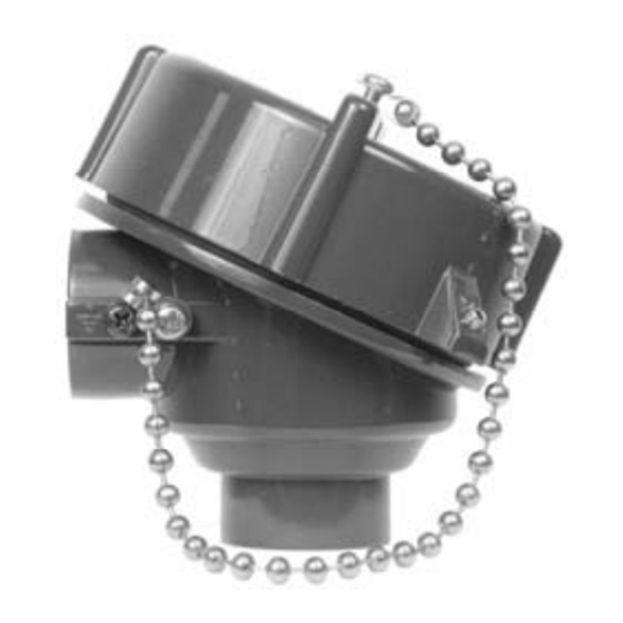
• Explosion-Proof or General Purpose Connection Head
• Transmitter Mounts Into Form B Connection Head
• Operating Temperature: -40 to 85°C
PRECISION DIGITAL CORPORATION
89 October Hill Road • Holliston MA 01746 USA
Tel (800) 343-1001 • Fax (508) 655-8990
®
HART
Non-HART
®
Protocol
www.predig.com
Advertisement
Table of Contents

Summary of Contents for Precision Digital Corporation ExSense Series
- Page 1 • Explosion-Proof or General Purpose Connection Head • Transmitter Mounts Into Form B Connection Head • Operating Temperature: -40 to 85°C PRECISION DIGITAL CORPORATION 89 October Hill Road • Holliston MA 01746 USA Tel (800) 343-1001 • Fax (508) 655-8990...
- Page 2 Anyone using this product for such applications does so at his/her own risk. Precision Digital Corporation shall not be held liable for damages resulting from such improper use. Limited Warranty Precision Digital Corporation warrants this product against defects in material or workmanship for the specified period under “Specifications”...
-
Page 3: Introduction
PD301 - PD306 Smart Temp Transmitters Instruction Manual INTRODUCTION The ExSense T Series is a line of smart temperature transmitters ® available with HART communication capabilities. All head mount models can be configured using a USB adapter and the free PC software available for download at www.predig.com. -
Page 4: Ordering Information
PD301 - PD306 Smart Temp Transmitters Instruction Manual ORDERING INFORMATION The following are a few examples of models that can be ordered. Use the online ExSense Builder to create a model to satisfy a particular application; choose other sensor types, lengths, and thermowells. Base Model Description PD301-C0... -
Page 5: Table Of Contents
PD301 - PD306 Smart Temp Transmitters Instruction Manual Table of Contents INTRODUCTION --------------------------------------------------------- 3 ORDERING INFORMATION ------------------------------------------ 4 SPECIFICATIONS ------------------------------------------------------- 7 General ----------------------------------------------------------------------------- 7 Accuracy & Ranges ----------------------------------------------------------- 10 Connection Head Ratings & Approvals ---------------------------------- 12 ... - Page 6 PD301 - PD306 Smart Temp Transmitters Instruction Manual Table of Figures Figure 1. Sensor & Loop Connectors ..........18 Figure 2. Sensor & 4-20 mA Connections ......... 18 Figure 3. Connections to PC with USB Modem ........ 19 ...
-
Page 7: Specifications
PD301 - PD306 Smart Temp Transmitters Instruction Manual SPECIFICATIONS Except where noted all specifications apply to operation at +25°C. General INPUT Universal RTD, TC, Resistance, or Voltage OUTPUT Two-wire 4-20 mA scalable ACCURACY & ±0.08% of span typical, INPUT RANGES see table on page 10 for details TEMPERATURE RTD: ±0.004°C/°C... - Page 8 PD301 - PD306 Smart Temp Transmitters Instruction Manual POWER SUPPLY 7.5 to 45 VDC, reverse polarity protected 790 Ω @ 24 VDC max or LOAD ((V supply - 7.5 V)/0.0208 A) Ω IMPEDANCE NORMAL MODE 64 dB at 50/60 Hz REJECTION ISOLATION 2 kV input-to-output...
- Page 9 PD301 - PD306 Smart Temp Transmitters Instruction Manual TIGHTENING Screw terminal connectors: 4.5 lb-in (0.5 Nm) TORQUE WEIGHT 1.18 oz (33.5 g); head mount transmitter only OVERALL Dia. 1.73" x 0.89" (44 mm x 22.5 mm) head DIMENSIONS mount transmitter only. Connection head, probe, and thermowell dimensions are not included.
-
Page 10: Accuracy & Ranges
PD301 - PD306 Smart Temp Transmitters Instruction Manual Accuracy & Ranges Accuracy Min Span Input Type Input Range (% of span) (4-20 mA) -200 to 850°C ±0.2°C or Pt100 10°C (18°F) (-328 to 1562°F) 0.08% -200 to 250°C ±0.5°C or Pt500 10°C (18°F) (-328 to 482°F) - Page 11 PD301 - PD306 Smart Temp Transmitters Instruction Manual Accuracy & Ranges (Continued) Accuracy Min Span Input Type Input Range (% of span) (4-20 mA) 0 to 1820°C ±2.0°C or 500°C ( 32 to 3308°F) 0.08% (900°F) -270 to 1000°C ±0.5°C or 50°C (90°F) (-454 to 1832°F) 0.08%...
-
Page 12: Connection Head Ratings & Approvals
PD301 - PD306 Smart Temp Transmitters Instruction Manual Connection Head Ratings & Approvals FM & CSA FM Approved & CSA Certified: Head Mount for use in Class I, Division 1, Groups B, C, and D; Dust-Ignition-proof for Class II, Division 1, Groups E, F, and G, Class III;... -
Page 13: Safety Information
PD301 - PD306 Smart Temp Transmitters Instruction Manual SAFETY INFORMATION CAUTION: Read complete instructions prior to installation and operation of the temperature transmitter. Installation and service should be performed only by trained service personnel. -
Page 14: Installation
PD301 - PD306 Smart Temp Transmitters Instruction Manual INSTALLATION For hazardous area applications, the installer is responsible for following all the appropriate hazardous area installation requirements. For Installation in USA: The Smart Temperature Transmitter must be installed in accordance with the National Electrical Code (NEC) NFPA 70. -
Page 15: Unpacking
PD301 - PD306 Smart Temp Transmitters Instruction Manual Unpacking Remove the temperature transmitter from box. Inspect the packaging and contents for damage. Report damages, if any, to the carrier. If any part is missing or the temperature transmitter malfunctions, please contact your supplier or the factory for assistance. Mounting The Head Mount Smart Temperature Transmitter is designed to mount on a DIN 43 729 Form B connection head using M4 screws. - Page 16 PD301 - PD306 Smart Temp Transmitters Instruction Manual Please refer to the graph below. The graph will provide an approximation of the temperature rise of the ExSense enclosure above ambient with different pipe/thermowell extension lengths and process temperatures. One should allow for some safety margin, as there are a number of variables that effect this information that cannot be easily accounted for.
-
Page 17: Connections
PD301 - PD306 Smart Temp Transmitters Instruction Manual Connections Make sure to turn off the power to the loop before accessing the screw terminals on the transmitter. To access the connectors on models PD303-306, remove the connection head cover. The connection diagram on the transmitter head clearly indicates where to connect the loop power and the various types of sensors. -
Page 18: Sensor & 4-20 Ma Output Connections
PD301 - PD306 Smart Temp Transmitters Instruction Manual Figure 1. Sensor & Loop Connectors Sensor & 4-20 mA Output Connections Figure 2. Sensor & 4-20 mA Connections... -
Page 19: Connections To Pc & Communicator
PD301 - PD306 Smart Temp Transmitters Instruction Manual Connections to PC & Communicator Figure 3. Connections to PC with USB Modem HART Connections to PC & Communicator Figure 4. Connections to PC & HART Communicator... -
Page 20: Setup And Programming
PD301 - PD306 Smart Temp Transmitters Instruction Manual SETUP AND PROGRAMMING HART communication requires a minimum of 250 Ω in the 4-20 mA loop. See Load Impedance specification to calculate the maximum load based on the power supply voltage (e.g. 650 Ω @ 24 VDC). The HART signal can be accessed using a HART communicator or a HART modem anywhere in the loop. -
Page 21: Temperature Transmitter Software
PD301 - PD306 Smart Temp Transmitters Instruction Manual Temperature Transmitter Software The HART Temperature Transmitter Software (HTTemp) can be downloaded free from www.predig.com. This is a simple user- friendly application to be used with the ExSense T Series only. The software allows the user to setup all the transmitter parameters available, using the USB modem or through the HART communication interface for models equipped with the HART protocol. - Page 22 PD301 - PD306 Smart Temp Transmitters Instruction Manual PDA8301 & PDA8302 USB Driver Installation 1. Connect the modem to the USB port and follow the on-screen instructions. 2. When prompted for the driver location, browse to the folder where the downloaded software was unzipped. If connected to the Internet, allow the program to search for the driver.
- Page 23 PD301 - PD306 Smart Temp Transmitters Instruction Manual 2. Click on “Hardware” – “Device Manager” – “Ports” 3. Here is the USB Serial Port associated with the new USB device (e.g. COM3). 4. If there are more USB Serial ports enabled, disconnect the modem from the USB port and notice which COM port disappears from the above screen.
-
Page 24: 4-20 Ma Loop Current Setup
PD301 - PD306 Smart Temp Transmitters Instruction Manual 4-20 mA Loop Current Setup The Current Setup window is used to trim the analog output to match the device reading the 4-20 mA current. 1. Click on Read next to the 4.000 mA box and type the actual mA reading corresponding to the 4 mA output (e.g. -
Page 25: Parameter Setup
PD301 - PD306 Smart Temp Transmitters Instruction Manual Parameter Setup The Parameter Setup window is used to set up the input type, range for the 4-20 mA, temperature units, and other settings related to the sensor and analog output. The Display Mode allows the selection of PV, mA, or % for the display. - Page 26 PD301 - PD306 Smart Temp Transmitters Instruction Manual Minimum Input Span The minimum input span is the minimum difference between the Zero value and the Full value signals required to generate the 4-20 mA output signal on the temperature transmitter (e.g. 18°F for RTDs). Refer to table on page 10 for the minimum span specifications.
-
Page 27: Hart Information
PD301 - PD306 Smart Temp Transmitters Instruction Manual HART Information The HART Information window allows the user to program or read the transmitter information and to modify the HART address for multi-drop applications. The Short address is 0 for standalone applications and 1-15 for multi- drop applications. -
Page 28: Calibration
PD301 - PD306 Smart Temp Transmitters Instruction Manual Calibration For most applications it should not be necessary to calibrate the 4-20 mA output. Instead of Calibration use the Parameter Setup to set the 4-20 mA output values. If a precise calibration is needed for a specific input type and range, follow the steps below: 1. -
Page 29: Graph Monitor
PD301 - PD306 Smart Temp Transmitters Instruction Manual Graph Monitor The Graph Monitor window is used to monitor the PV, mA, and %. Monitor the three variables at once or just one of the variables. A log data file can be saved for later viewing; it contains the time, data value, and units. -
Page 30: Application
PD301 - PD306 Smart Temp Transmitters Instruction Manual APPLICATION PD306 HART Transmitter & Remote Display In this application the Smart HART Head Mount Temperature Transmitter is being powered by the PD6000 dual-scale meter; the meter displays the temperature on the top display and the mA current on the bottom display. -
Page 31: Mounting Dimensions
PD301 - PD306 Smart Temp Transmitters Instruction Manual MOUNTING DIMENSIONS All units: inches [mm] Figure 5. Head Mount Transmitter Dimensions Figure 6. Connection Head Dimensions... -
Page 32: Temperature Probes
PD301 - PD306 Smart Temp Transmitters Instruction Manual TEMPERATURE PROBES RTD and TC probes may be specified and order separately using the following Model Configuration chart. ERP Field Location Model Number Sensor Type P1 = Pt100 RTD TJ = Type J TC TK = Type K TC TT = Type T TC Sensor Lead Length... -
Page 33: Thermowells
PD301 - PD306 Smart Temp Transmitters Instruction Manual THERMOWELLS Thermowells may be ordered separately using the following sample drawing and the Model Configuration chart. 1.75" 0.50" 0.50" NPSM 2.50" Q dia. dia. Bore: 0.260" 0.25" A = U + 1.50"... - Page 34 PD301 - PD306 Smart Temp Transmitters Instruction Manual Thermowell Model Configuration Model Description PDAT1 Thermowell, Stepped Stem, Threaded Shank Dia. CODE "H" HEX(A/F) "P" Process Thread 1/2" NPT 5/8" 1 1/8" 3/4" NPT 3/4" 1 1/8" 1" NPT 7/8" 1 3/8" CODE Material Of Construction SS304...
-
Page 35: Troubleshooting
PD301 - PD306 Smart Temp Transmitters Instruction Manual TROUBLESHOOTING If the Smart Temperature Transmitter is not working as expected, refer to the recommendations below. Symptom Check/Action • No communication Voltage too low • Check loop impedance • Fault or alarm current Defective or open sensor (≤3.6 mA or ≥... - Page 36 PD301 - PD306 Smart Temp Transmitters Instruction Manual How to Contact Precision Digital • For Technical Support: Call: (800) 610-5239 or (508) 655-7300 Fax: (508) 655-8990 Email: support@predig.com • For Sales Support: Call: (800) 343-1001 or (508) 655-7300 Fax: (508) 655-8990 Email: sales@predig.com •...
Need help?
Do you have a question about the ExSense Series and is the answer not in the manual?
Questions and answers