Advertisement
Quick Links
Advertisement

Related Manuals for Balt 27531


Summary of Contents for Balt 27531
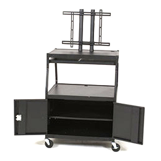
- Page 1 #27531 Wide Body LCD TV Cart with 2 Pull-out Shelves & Locking Cabinet Assembly Instructions...
- Page 2 #27531 Wide Body LCD Cart Part Drawing Description Part Drawing Description Formed Leg ”O” 2 EA Inner Slide 14 2 EA Outer Slide 14 2 EA Formed Leg ”X” 2 EA Inner Slide 18 2 EA Top Shelf 2 EA...
-
Page 3: Hardware List
#27531 Wide Body LCD Cart Hardware List Sq Hd Screw M8x15mm 24 EA Screw Pan HD M4X10mm 18 EA for slide assembly Screw M5X70mm Pan Hd 2 EA electrical Screw M8X25mm Pan Hd 4 EA Screw M6X35mm Pan Hd 4 EA... - Page 4 #27531 Wide Body LCD Cart Assembly Diagram BEFORE HROUGH NSTRUCTIONS FROM BEGINNING TO END STARTING TO ASSEMBLE UNIT Identify and Separate all the Parts and Hardware. Attach 2 Legs (P-1) and 2 Legs Illustration # 1 (P-2) to the Top Shelf (P-3) using 8 screws (A), and 8 Nuts (B).
- Page 5 Note: Be sure that Door stop on Bottom Illustration #3A Shelf (P5) is oriented towared the front of cart. Grommets in Top Shelf (P3) and Grommet Middle Shelf (P4) are toward the back as shown in illustration # 3A. Attach 2 side Panels (P-6) and Middle Shelf (P-4) to the 4 Legs (P-1 &...
- Page 6 Attach Left and Right Support Tubes Illustration #4 (P-21 & P-22) to Top Shelf (P-3) using 2 screws (A4) and 2 Washers (C2) as shown P-22 P-21 in illustration # 4. Attach Cord Winder (P-25) and Electrical Outlet (P-26) to Top Shelf (P-3)using 2 screws (A2) and 2 Nuts (B2).
- Page 7 Illustration #6 12.) Attach Left Door w/Lock (P-8) to the Left Front Leg (P-1) using 3 screws (A7) and 3 Washers (C1) as shown in illustration # 6. 13.) Attach Right Door (P-9) to the Right Front Leg (P-2) using 3 screws (A7) and 3 Washers (C1).
- Page 8 P-11 17.) Attach 1 Outer Slide 14 (P-14) and 1 Outer Slide 18 (P-16) to the Left Laptop Support (P-11) using 5 screws (A1) and 5 Hex Nuts (B1) as shown in illustration #8. P-14 Illustration #8 P-12 P-16 Attach 4 angle Brackets 18.) (P-10) to the Left and Right Laptop Supports...
- Page 9 Insert 4 Shelf Supports (P-19) in the slots in the 2 Side Panels (P-6) as shown in illustration # 11. 24.) Place Cabinet Shelf (P-20) on top of Shelf Supports (P-19) as shown in illustration # 11. P-19 P-19 P-20 Illustration #11 27531 -01/18/08...
Need help?
Do you have a question about the 27531 and is the answer not in the manual?
Questions and answers