Table of Contents
Advertisement
Advertisement
Table of Contents

Related Manuals for MicroRidge Gageway Pro Series

Summary of Contents for MicroRidge Gageway Pro Series
- Page 3 GageWay Pro Interfaces Copyright © 2017-2020 MicroRidge Systems, Inc. All rights reserved. No parts of this work may be reproduced in any form or by any means - graphic, electronic, or mechanical, including photocopying, recording, taping, or information storage and retrieval systems - without the written permission of the publisher.
-
Page 5: Table Of Contents
Custom Measurement Format ........................Custom Read Switch Sequence ........................Send Commands to Host ........................Utilities Menu ........................... Available Serial Ports ........................Default File Folder ........................Chapter 4 ComTestSerial ........................... Chapter 5 Computer Commands ........................... Copyright © 2017-2020 MicroRidge Systems, Inc. - Page 6 Contents GageWay Pro Interfaces Chapter 6 Accessories ........................... Chapter 7 Warranty Information ........................... Chapter 8 Contact MicroRidge ........................... Copyright © 2017-2020 MicroRidge Systems, Inc.
-
Page 7: Chapter 1 Introduction
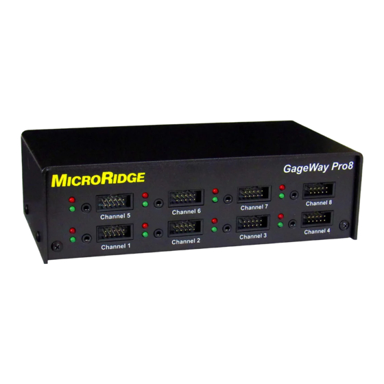
GageWay Pro8, 8-Port interface The GageWay Pro interfaces replace the GageWay Series (GageWay3 and GageWay5) and GageWay Mx (Mx4 and Mx8) interfaces previously available from MicroRidge Systems. The GageWay Pro computer commands are, in most cases, identical to the commands used by the previous GageWay interfaces. - Page 8 If you are viewing the PDF version of this User's Guide, you will see page numbers to the right of the links within the PDF document. For example the number to the right of the Contact MicroRidge Systems link indicates the actual page number this link is directed to. Copyright © 2017-2020 MicroRidge Systems, Inc.
- Page 9 EU, REACH compliance is having a global effect. All current MicroRidge produced products are in compliance with REACH and do not contain any of the currently listed SVHC (substance of very high concern) in concentrations of 0.1% or above.
-
Page 11: Chapter 2 Gageway Pro Interfaces
Pro2 can be sent to the USB Serial Port or the USB Keyboard Wedge Port. Power to the interface is supplied via the USB Keyboard Wedge port or the USB Serial Port. Multifunction Serial Port can be used to connect an additional serial device to the interface. Copyright © 2017-2020 MicroRidge Systems, Inc. -
Page 12: Gageway Pro4
Back panel contains a DB9 Output Serial Port that allows for sending data to a device that does not support USB. § The Multifunction Serial Port can be used to connect an additional serial device to the interface and to chain Pro4 and Pro8 interfaces. Copyright © 2017-2020 MicroRidge Systems, Inc. -
Page 13: Gageway Pro8
Gage readings can be initiated by any of the following methods: § Press a foot or hand switch (external read switch). § Press the read button on the gage cable. § Send a command from the host computer. Copyright © 2017-2020 MicroRidge Systems, Inc. - Page 14 Once the interfaces are chained, most of the read commands and features that can be used with a single interface can be used with the chained interfaces. Refer to the Chaining Interfaces section for more detail. Copyright © 2017-2020 MicroRidge Systems, Inc.
-
Page 15: Connecting To A Computer
This driver is developed by FTDI and supports the FTDI USB chip used in the GageWay Pro. You can also obtain a copy of this driver from the following web sites. § MicroRidge web site at www.microridge.com/downloads.htm. The driver on the MicroRidge web site is only for use with Windows. §... - Page 16 USB cable to power the GageWay Pro interface. A USB AC adapter is not included with the standard interface purchase. A USB AC adapter along with connecting cables can be purchased from MicroRidge. The part number for this adapter and cables for North America is ADT-USB- NA-KIT.
-
Page 17: Back Panel Buttons
If a device is found, the green LED will flash several times. If a device is not found, the red LED will flash several times. Copyright © 2017-2020 MicroRidge Systems, Inc. -
Page 18: Autobaud Detect
The following baud rates can be used with and detected by a GageWay Pro interface. If none of these baud rates match the setting of your serial device, you must change the baud rate setting for your serial device. § 1200 § 2400 § 4800 § 9600 § 14.4K § 19.2K Copyright © 2017-2020 MicroRidge Systems, Inc. - Page 19 Converter cables were detected. At this point you have 10 seconds to send a data packet to the GageWay Pro. When the AutoBaud detection process has finished, the LEDs will do one of the following: LEDs turn off No data was received. The baud rate and communication parameters remain unchanged. Copyright © 2017-2020 MicroRidge Systems, Inc.
-
Page 20: Configuring The Gageway Pro
Output Serial Port on the next interface. § Each interface in the chain must be powered via the USB port. Power kits with connecting cables are available from MicroRidge for powering the Slaves. Copyright © 2017-2020 MicroRidge Systems, Inc. - Page 21 USB & Output serial ports radio buttons on the Home Tab of the Setup Program. To be safe, when chaining interfaces set the Master communications baud rate to 57.6K or 115.2K whenever possible. Copyright © 2017-2020 MicroRidge Systems, Inc.
-
Page 22: Testing Your Serial Device
GageWay Pro handles any necessary baud rate and/or communication parameters conversion. 2.12 Firmware Updates Firmware updates for a GageWay Pro are available on the MicroRidge web site at www.microridge.com/downloads.htm. You will need to download and install the firmware update Copyright © 2017-2020 MicroRidge Systems, Inc. - Page 23 PC. The firmware updates are done via the USB cable connected to the USB Serial Port and it is not necessary for you to open the interface. The same update is used for the Pro2, Pro4 and Pro8 interfaces. Copyright © 2017-2020 MicroRidge Systems, Inc.
-
Page 25: Chapter 3 Setup Program
To make it apparent that the GageWay Pro needs to be updated with the parameters modified in the setup program, a message in red text green text is displayed on each of the tabs. Copyright © 2017-2020 MicroRidge Systems, Inc. -
Page 26: Keyboards
GageWay Pro shows what the previous keyboard type was and what the new keyboard type is. An example of entering the <$KF command to switch to the France keyboard is shown below. <$KF Previous keyboard type = English (United States, QWERTY) New keyboard type = French (France, AZERTY) Copyright © 2017-2020 MicroRidge Systems, Inc. -
Page 27: Keyboard Wedge Transfer Rate
PC. If you enter characters such as {LF}, {\x0a}, {\xa2}, etc., the GageWay Pro will not send these characters to the wedge port. If you are sending the data out the RS-232 port, the GageWay Pro will send these special characters. Copyright © 2017-2020 MicroRidge Systems, Inc. -
Page 28: Program Tabs
By displaying information about the active control, you have quick and easy access to information about the control. Copyright © 2017-2020 MicroRidge Systems, Inc. -
Page 29: Home Tab
Setup Program matche the parameters stored in the Pro4. If this text was red, it would mean that you need to send the revised parameters to the GageWay Pro. Copyright © 2017-2020 MicroRidge Systems, Inc. -
Page 30: Pro2, Pro4 & Pro8 Tabs
There are a few External Read Switch (column 9) options that have a dialog where you can enter additional information. If the text in the External Read Switch cell contains the string (setup), you can double-click the cell to view the setup dialog. Copyright © 2017-2020 MicroRidge Systems, Inc. -
Page 31: Setup Dialogs
This dialog is accessed by double-clicking a cell in the RS-232 Setup Column. If the cell you are trying to double-click has a light red background, this means that the Gage Type selected does Copyright © 2017-2020 MicroRidge Systems, Inc. - Page 32 Configuring the dialog for the serial device can be very easy if you know what you are trying to do. Copyright © 2017-2020 MicroRidge Systems, Inc.
-
Page 33: Custom Measurement Format
Counter field. This field outputs a counter that increments with each new measurement. The counter will roll over to 1 when its value exceeds the size of the field. Copyright © 2017-2020 MicroRidge Systems, Inc. - Page 34 \ character before the character. The following shows 2 examples: To add the text chan, you would enter chan. To add the text Chan, you would enter \Chan. Copyright © 2017-2020 MicroRidge Systems, Inc.
-
Page 35: Custom Read Switch Sequence
If you check the "Set Read sequence 3 to 150 characters and disable Read sequence 4" check box, you combine Read sequences 3 and 4 to create a 150-character sequence. When this box is checked you have access to 2 25-character sequence and 1 150- character sequence. Copyright © 2017-2020 MicroRidge Systems, Inc. - Page 36 72. Read Channel 52. Read Channel 53. Start using Channel Group 1. A to Z now represents channels 1 to 26 Read channel 3. Read channel 4. Copyright © 2017-2020 MicroRidge Systems, Inc.
- Page 37 Get a specified number of TIR readings. The readings will stop when the specified number of readings have been obtained or the interface receives a <Sc stop continuous read command. t155D Get 155 TIR readings from channel D. Copyright © 2017-2020 MicroRidge Systems, Inc.
-
Page 38: Send Commands To Host
You can specify a single string up to 31 characters or 2 string up to 15 characters each. The string(s) that are created in this dialog, are the only Host Command strings that can be used for the interface. Copyright © 2017-2020 MicroRidge Systems, Inc. -
Page 39: Utilities Menu
Program will first check the serial port where a GageWay Pro was previously found. If a GageWay Pro is not found on the previous port, the Setup Program will search each of the checked serial ports shown in this dialog. Copyright © 2017-2020 MicroRidge Systems, Inc. - Page 40 Be sure the GageWay Pro is connected to the appropriate USB port on your PC before starting your application. Remember, the serial port on your PC is not created until the GageWay Pro has been connected. Copyright © 2017-2020 MicroRidge Systems, Inc.
-
Page 41: Default File Folder
PC. You must manually save the file to your PC. If you contact technical support for assistance in setting up a GageWay Pro, you may be asked to email a copy of the setup file to technical support. Copyright © 2017-2020 MicroRidge Systems, Inc. -
Page 43: Chapter 4 Comtestserial
× Copyright (< Get copyright and some setup information from the GageWay Pro. Chan 1 Copyright (<G*01) Get copyright and some setup information for channel 1. Commands Help (<H) Display computer commands help information. Copyright © 2017-2020 MicroRidge Systems, Inc. - Page 44 Read all of the gages. Gages (<T) Show a list of the gages connected to the GageWay Pro. Additional copies of ComTestSerial can also be downloaded from the ComTestSerial page on the MicroRidge web. Copyright © 2017-2020 MicroRidge Systems, Inc.
-
Page 45: Chapter 5 Computer Commands
List of gages attached to the interface. <V Get version information for the communications processor. × <G Get copyright information for the channel c gage module. <GVc Get version information for the channel c gage module. Copyright © 2017-2020 MicroRidge Systems, Inc. - Page 46 Multifunction Serial Port and ComTestSerial. This command can be used to verify communications with your serial device and to understand what data is being sent from your serial device. Refer to the Testing Your Serial Device section for more information. Copyright © 2017-2020 MicroRidge Systems, Inc.
- Page 47 Show the data in the RS-232 buffer for channel c. This command will only output information if a Level Converter cable is connected to the channel. <GLc Blink the gage module LEDs for channel c. <T List of gages attached to the interface. Copyright © 2017-2020 MicroRidge Systems, Inc.
- Page 49 Accessories Accessories Several accessories are available for use with the GageWay Pro interfaces. These items are available for purchase directly from the MicroRidge web site. Level Converter Cable 24" cable that converts the RS-232 voltage levels to acceptable levels that can be used by the GageWay Pro interfaces.
- Page 50 This item is required if you are not connecting the interface to a computer through one of the USB ports on the back of P/N: ADT-USB-NA-KIT the interface. A Power Kit is required for Slave interface in a chained configuration. Copyright © 2017-2020 MicroRidge Systems, Inc.
- Page 51 MicroRidge in writing of such defect within thirty (30) days of discovery and returns such products in accordance with the MicroRidge instructions. No products may be returned without MicroRidge prior written authorization.
- Page 53 MicroRidge Systems, Inc. 56888 Enterprise Drive Sunriver, OR 97707 Note: There is no mail delivery to this address. This address should only be used for package delivery services such as UPS, FedEx, etc. Web: www.microridge.com Copyright © 2017-2020 MicroRidge Systems, Inc.
- Page 55 - F - Firmware updates - G - Gage readings - K - Keyboard wedge - L - LEDs - R - Reset button RoHS RS-232 Gage Test Mode 16, 37 - S - Setup Program Copyright © 2017-2020 MicroRidge Systems, Inc.
Need help?
Do you have a question about the Gageway Pro Series and is the answer not in the manual?
Questions and answers