Advertisement
Quick Links
Build Your Own Clone
Classic Compressor
Kit Instructions
Warranty:
BYOC, LLC guarantees that your kit will be complete and that all parts and components
will arrive as described, functioning and free of defect. Soldering, clipping, cutting,
stripping, or using any of the components in any way voids this guarantee. BYOC, LLC
guarantees that the instructions for your kit will be free of any majors errors that would
cause you to permanently damage any components in your kit, but does not guarantee
that the instructions will be free of typos or minor errors. BYOC, LLC does not
warranty the completed pedal as a whole functioning unit nor do we warranty any of the
individual parts once they have been used. If you have a component that is used, but
feel it was defective prior to you using it, we reserve the right to determine whether or
not the component was faulty upon arrival. Please direct all warranty issues to:
sales@buildyourownclone.com This would include any missing parts issues.
Return:
BYOC, LLC accepts returns and exchanges on all products for any reason, as long as
they are unused. We do not accept partial kit returns. Returns and exchanges are for the
full purchase price less the cost of shipping and/or any promotional pricing. Return
shipping is the customers responsiblity. This responsibility not only includes the cost of
Advertisement

Subscribe to Our Youtube Channel
Related Manuals for BYOC Classic Compressor Kit

Summary of Contents for BYOC Classic Compressor Kit
- Page 1 Kit Instructions Warranty: BYOC, LLC guarantees that your kit will be complete and that all parts and components will arrive as described, functioning and free of defect. Soldering, clipping, cutting, stripping, or using any of the components in any way voids this guarantee. BYOC, LLC...
- Page 2 That being said, we will do our best to help you as much as we can. Our philosophy at BYOC is that we will help you only as much as you are willing to help yourself. We have a wonderful and friendly DIY discussion forum with an entire section devoted to the technical support and modifications of BYOC kits.
-
Page 3: Table Of Contents
CLASSIC COMPRESSOR KIT INSTRUCTION INDEX Parts Checklist ....page 4 - 5 Populating the Circuit Board ....page 6 - 16 Main PCB Assembly .........page 17 - 19 Wiring................page 20 - 23 Installing the IC and Finishing Up.......page 24 Operation Overview..........page 25... -
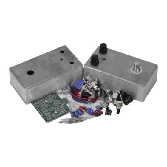
Page 4: Parts Checklist
Parts Checklist for BYOC Classic Compressor Kit Resistors: 1 - 4k7 (yellow/purple/black/brown/brown) 6 - 10k (brown/black/black/red/brown) 1 - 15k (brown/green/black/red/brown) 2 - 27k (red/purple/black/red/brown) 1 - 56k (green/blue/black/red/brown) 2 - 150k (brown/green/black/orange/brown) 2 - 220k (red/red/black/orange/brown) 3 - 470k (yellow/purplw/black/orange/brown) - Page 5 1 - B500k audio (SENSITIVITY) 1 - 2k trimpot Hardware: 1 - drilled enclosure w/ 4 screws 1 - byoc classic compressor PCB 1 - 3PDT footswitch 2 - knobs 1 - AC adaptor jack 1 - ¼ mono jack 1 - ¼...
-
Page 7: Populating The Circuit Board
Populating the Circuit Board STEP 1: Add the diodes. Be sure to match the end of the diode with the stripe to the layout on the PCB. The stripped end should go in the square solder pad. - Page 8 STEP 2: Add the resistors . Resistors are not polarized, so it does not matter which end goes in which solder pad. Take your time and be sure not to confuse similarly banded resistors such as the 470k with the 4k7 or the 10k with the 100k. If you have difficulty reading the color bands, use a digital multimeter to test the value of each resistor.
- Page 9 Step 3: Add the trim pot. The space on the PCB has 5 holes, but the trim pot will only have 3 leads. This is so that the PCB can accept a variety of different brands and styles of trim pot. There should only be 1 way that your trim pot will fit into the PCB without having to bend the leads.
- Page 10 STEP 4: Add the 8 pin IC socket. ONLY SOLDER THE SOCKET! NOT THE ACTUAL IC! This is a socket. The socket gets soldered to the PCB. The ICs get inserted into the sockets. The actual IC chip itself, never gets soldered. You will insert the IC into the socket after the entire pedal has been built.
- Page 11 NOTE: This PCB is designed with the standard EBC pinout. Both the 2N5088 and 2SC1849 transistors that are supplied with BYOC kits have the standard EBC pinout. However, some brands of 2SC1849 have a BCE pinout. If you have sourced transistors...
- Page 12 Step 6: Add the film and ceramic disc capacitors. These are not polarized and can be inserted into the PCB either way.
- Page 13 STEP 7: Add the aluminum electrolytic capacitors. These are polarized. The positive end will have a longer lead and should go in the square solder pad. The negative end will have a shorter lead with a black or white stripe running down the body of the capacitor.
- Page 14 Step 8: Add the battery snap. Thread the solder ends of the battery snap into the strain relief holes from the bottom solderside of the PCB and out through the top. Insert the solder ends of the battery snap wires into the topside of their respective solder pads. Solder on the bottom side of the PCB.
- Page 15 Step 8: Add wires to the IN, OUT, RING, and two Ground eyelets. Start by cutting four 2.5 pieces of wire and one 1.5 piece of wire. Strip 1/4 off each end and tin the ends. Tinning means to apply some solder to the stripped ends of the wires. This keeps the strands from fraying and primes the wire for soldering.
-
Page 16: Main Pcb Assembly
Main PCB Assembly Step 1: Mount the DC adapter jack to the enclosure. The sleeve disconnect terminal of the DC adapter jack connects directly to the positive terminal of the battery via the PCB. The sleeve disconnect terminal is connected to the sleeve terminal when there is no DC adapter plugged into the jack. - Page 17 Step 2: Connect the TIP (negative) terminal of the DC adaptor jack to the eyelet on the PCB with 2 inches of hook up wire. Connect the SLEEVE of the DC adaptor jack to the eyelet on the far right side of the PCB with 2 inches of hook up wire.
- Page 18 Step 3: Flip the PCB over so that the bottom or solder side is up. Insert the A100k(LEVEL), B500k(SUSTAIN) potentiometers, and the LED into the bottom side of the PCB. DO NOT SOLDER ANYTHING YET!!! The LED will have one lead that is longer than the other.
- Page 19 Step 4: Hold the PCB in one hand so that the component side of the PCB is in the palm of your hand and the bottom side with the pots, toggle switch and LED is facing up. Now use your other hand to guide the predrilled enclosure onto the PCB assembly so that the pots and LED all go into their respective holes.
-
Page 20: Wiring
Wiring Step 1: Install the 1/4 jacks to the enclosure. Step 2: Install the footswitch. Orient the footswitch so that the flat sides of the solder lugs are like the diagram below. NOTE: There are no actual number markings on the footswitch. - Page 22 Step 3: Connect the pre stripped and tinned wires to the 1/4 jacks. Step 4: · Cut 4 x 3/4 pieces of wire. Strip 1/8 off each end. These will be used to connect lugs/eyelets 1, 2, 7, & 8 ·...
- Page 23 · Cut 3 x 2 pieces of wire. Strip 1/4 off each end. These will be used to connect the tip and sleeve of the IN jack and the tip of the OUT jack to the PCB. · Cut 1 x 1.5 peice of wire. Strip 1/4 off each end. This will be used to connect the ring of the IN jack to the ring eyelet on the PCB.
-
Page 24: Installing The Ic And Finishing Up
Installing the IC and Finishing Up... - Page 26 Once you've install the IC, it's time to test the pedal. If you don't get any sound at first, don't worry. You will need probably need to adjust the trimpot. If your trimpot isn't already set at the middle of its rotation, do so. This may or may not be the optimal setting for the trimpot, but it should definitely produce sound and be a good starting point for fine tuning.
-
Page 27: Operation Overview
Operating Overview LEVEL & SUSTAIN: Do you really need an explaination of what these knobs do? DC power supply - Use a 2.5mm negative tip (this is your standard guitar fx style adapter) 9, 12, 15, or 18VDC adapter. The higher voltage will give you more headroom and output. - Page 28 Output Impedance - 100k ohms...
- Page 30 Please visit http://buildyourownclone.com/board for any technical support copyright 2010 B.Y.O.C., LLC...
Need help?
Do you have a question about the Classic Compressor Kit and is the answer not in the manual?
Questions and answers