Table of Contents
Advertisement
Advertisement
Table of Contents

Summary of Contents for WAVESTREAM RMC-RRS011-HE01
- Page 1 Redundancy Controller RMC-RRS011-HE01 Operation Manual W A V E S T R E A M 545 West Terrace Drive San Dimas, CA 91773 Phone: 909.599.9080 / 1.877.214.6294 Fax: 909.599.9082 http://www.wavestream.com Copyright © 2011 Wavestream Corporation. All rights reserved. Document Number: 90-005-0030_E...
- Page 2 Spatial Power Advantage™ is a trademark of Wavestream Corporation. All other trademarks are properties of their respective owners. The information supplied in this operation manual is provided by Wavestream Corporation as a service to customers. Although every effort has been made to verify the completeness and accuracy...
- Page 3 To repair damage or malfunction caused by the use of non-standard ancillary equipment. To service a product that has not been previously approved in writing by Wavestream Corporation. N o t e Opening or removing any component or sealed area will immediately void the warranty.
-
Page 4: Table Of Contents
J2 – Alarms and General Purpose Outputs ..............11 J3 – Tx Waveguide Switch Controller & Position Sense ........... 12 J4 – Wavestream SSPS-A Interface ................12 J5 – Rx Waveguide Switch Controller & Position Sense ........... 13 J6 – Wavestream SSPA-B Interface ................13 J7 –... -
Page 5: Introduction
About This Manual This operation manual provides information and instructions for installation and operation of Wavestream equipment. It should be used by trained field technicians, or system engineers, responsible for satellite and broadcast networks. This manual refers to a waveguide switch as a baseball switch. A baseball switch is an industry standard name for a certain type of waveguide switch. -
Page 6: Safety
Shock Hazard. Do not open the unit. High voltages are present inside the unit. Service may only be performed by Wavestream. There are no user serviceable parts. Do not attempt to service this product yourself. Any attempt to do so void any and all warranties. -
Page 7: Specifications
Redundancy Controller Page Specifications Performance Switch operation Manual or automatic, user selectable Muting Wavestream SSPAs/BUCs: automatic muting of transmission when baseball switch switches between units. Switching time Less than 1 second Supported units Wavestream: 8-40 W Ku-Band SSPA / BUC... -
Page 8: Dimensions
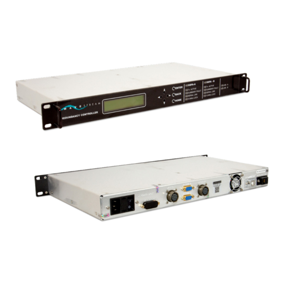
SSPA-A / SSPA-B M&C cable 15-pin discrete output / alarms cable Ethernet cable (optional) USB (optional for firmware upgrade) AC power cable Technical Support Technical support is available by email at support@wavestream.com. Document Number: 90-005-0030_E... -
Page 9: System Description
Off = no system fault is sensed. SERIAL LINK: Green LED on = a serial link to Wavestream SSPA/BUC is established. Off = the system status is ok or the RMC is connected to a non-Wavestream SSPA. 10MHz LOCK: Green LED on = a 10 MHz Reference signal is supplied to the SSPA. -
Page 10: Back
Redundancy Controller Page Back Port Name Description Connector On the Unit Mating Connector 90-264 VAC Primary power, 110 W @ C13 power plug 50/60 Hz 120 VAC Fuse 5x20mm 1A slow blow long time lag fuse Power Enables/disables unit power switch Alarms Alarms, general purpose... -
Page 11: J1 - Ac Input Power
AC neutral [top pin] Ground [center pin] J2 – Alarms and General Purpose Outputs Pins 1-11 are TTL logic. Must use when connecting to non-Wavestream SSPAs for control of discrete inputs. Description Wavestream SSPA / BUCs Non-Wavestream SSPA General input LNB-A fault... -
Page 12: J3 - Tx Waveguide Switch Controller & Position Sense
Twist with pin C and B Relay Position Sense 1A Twist with pin E and D Signal Ground Relay Position Sense 1B Twist with pin F and E J4 – Wavestream SSPS-A Interface Description Notes RS485 Rx- Twist with pin 7 RS485 Tx+... -
Page 13: J5 - Rx Waveguide Switch Controller & Position Sense
Relay Position Sense 2 A Twist with pin E Signal Ground Twist with pin D and F Relay Position Sense 2 B Twist with pin D J6 – Wavestream SSPA-B Interface Description Notes RS485 Rx- Twist with pin 7 RS485 Tx+... -
Page 14: J8 - Ethernet Console A Port
Redundancy Controller Page J8 – Ethernet Console A Port Use Standard CAT 5e Cable. Description Notes ENET TX+ ENET TX- ENET RX+ ENET RX- Document Number: 90-005-0030_E... -
Page 15: Installation And Configuration
Page Installation and Configuration Wavestream’s RMC Controller automatically or manually switches to a secondary SSPA (Solid State Power Amplifier) when system configuration requires redundancy. The controller can be manually configured and controlled from the front panel or remotely configured and controlled with Wavestream provided software via the Ethernet console port. -
Page 16: Waveguide Connection Diagram
Redundancy Controller Page Waveguide Connection Diagram Use this configuration when a non-Wavestream switch is being used in the system. The switch must be a 24 VDC drive switch. R107 Document Number: 90-005-0030_E... -
Page 17: Preparation
Redundancy Controller Page Preparation Required Tools / Supplies Torque driver Cable manufacturing tools Installation Precautions / Prerequisites C A U T I O N Moisture sensitive. The unit is not weatherized. Install in a weatherized location using good commercial practice and UV-rated materials. Inspection and Unpacking ... - Page 18 ON/OFF switch on the RMC back panel. 3. The RMC displays the Wavestream graphic while the self test runs. 4. At the completion of the self test, all of the LEDs will flash and stay on for 2-3 seconds, then flash again.
- Page 19 Install the cables J2 through J8 into the back of the RMC as applicable. Wavestream SSPAs / BUCs This procedure assumes that there are two operating Wavestream SSPAs / BUCs and that the waveguide switches are already installed. W A R N I N G Wiring.
-
Page 20: Operation
Redundancy Controller Page Operation MENU/CONTROL: SSPA-A SSPA-B TX SW RX SW DISC.OUT REDUNDANCY Menu Map Document Number: 90-005-0030_E... -
Page 21: Menu Definitions
A=1 and 2, 3 and 4 B=1 and 4, 2 and 3 DISC. OUT Configure discrete outputs. For non-Wavestream units, these pins must be connected; otherwise the unit will not be muted during transition. SSPA-A/B Lists submenus that may be accessed Front Panel LEDS Enable/disable the front panel LEDs. -
Page 22: Rmc Front Panel Status And Control
Redundancy Controller Page Redundancy Select the redundancy that the units are configured for 1:1 simplex redundancy [OFF/ON] Default is on. If the primary unit goes into summary fault mode, the RMC automatically switches transmit to the secondary unit. Rx is not automatically switched. -
Page 23: Quick Navigation
Redundancy Controller Page Quick Navigation ENTER 1. Press to return to the Monitor/Home position Home BACK HOME 2. Press to access the Menu/Control. Enter ENTER BACK HOME 3. Use the arrow keys to select a submenu, press to access it. Enter ENTER BACK... - Page 24 Out3 General Output 3 General Output 3 For non-Wavestream SSPAs these pins must be connected and set to mute the unit during transition. Wavestream units are automatically muted when the baseball switch transitions from one SSPA to another. Go to Transmit Inhibit for information to add a transmit inhibit switch to the RMC.
-
Page 25: Gui Installation
System and Software Requirements Connection via Ethernet only. Controller Computer Specifications Operating system Windows Required Equipment / Tools Wavestream software CD Setup.exe wavestreamgui.exe Lantronix DeviceInstaller.exe (www.lantronix.com) GUI Installation 1. Copy all of the files from the CD to a directory on the controller. - Page 26 Redundancy Controller Page 2. Click . A list of available ports will be displayed in the adjacent window. Search Serial Ports Click the dropdown arrow to list all available ports. Select Ethernet. 3. Click to start communication between the unit and the PC. Start r108 4.
-
Page 27: Gui Description
Redundancy Controller Page GUI Description Controls Active control functions allowed from the GUI are shown as buttons. When a button is clicked the command is sent to the unit. Dropdown menus are used to access local GUI functions. Status All digital monitor signal states have a description next to the name of the monitor. For example, Summary Fault will display either Ok or Fault depending on the state. - Page 28 Redundancy Controller Page The following SSPA status definitions are displayed on the GUI and indicate the status of the SSPAs. The following definitions can also be found in the appropriate manual associated with each power amplifier. For complete definitions, refer to the SSPA manual. To view the redundant SSPA information, click the pull down menu.
- Page 29 Redundancy Controller Page RMC External Discretes In In 0: High– J2 Pin1 is high (5V). Low– J2 Pin1 is low (0V). High – J2 Pin 2 is high (5V). In 1: Low – J2 Pin 2 is low (0V). High – J2 Pin 3 is high (5V). In 2: Low –...
- Page 30 Redundancy Controller Page Unit Serial Connection Green dots in lower Serial connection activity is indicated by a series of dots on the bottom left of the left GUI screen. If the series of dots is moving, then the GUI is connected to the unit. ...
- Page 31 Redundancy Controller Page Reset Fault Mode Reset a reflected power fault. Calibrated Telemetry – returns calibrated telemetry values (i.e. voltages, Advanced currents, RF power). Raw Telemetry – displays raw telemetry values (internal measurement). Splash Screen – enable / disable displaying the splash screen when starting the GUI application.
-
Page 32: Power On
1. Verify that all cables, units, and waveguides are connected to the RMC. 1. Turn on the computer where the Wavestream GUI is loaded and open the GUI application by double-clicking the Wavestream icon. 2. Turn on power to the RMC. -
Page 33: Set Or Change The Step Attenuation
Redundancy Controller Page Set or Change the Step Attenuation r108 Press the up and down arrows in the Step Attenuation field to set the gain to a specific value. Click , to save the step attenuation setting upon boot- Save Settings →... -
Page 34: System Faults And Activity
Review the faults (listed in the log). Check System Faults If a latching fault occurs (for example, reverse power exceeds the threshold) press Reset Fault Mode the Wavestream GUI to clear the latching fault. From the menu, press Log → Maximize Home ... -
Page 35: Transmit Inhibit
Redundancy Controller Page Transmit Inhibit Shorting /Inhibit (pin 11) to Ground (pin 10) of J2 mutes all units connected to the RMC, this configuration may be used to implement a transmit inhibit switch on the system: When transmit inhibit is activated the display for all connected amplifiers/BUCs will instantly change showing that the connected amplifiers/BUCs have been muted. -
Page 36: Troubleshooting
Possible power supply problem. Return RMC to Wavestream. Any problems that occur past these simple tests probably indicate internal failures and the RMC must be returned to Wavestream. See front section of this manual for returning procedures. Document Number: 90-005-0030_E... -
Page 37: Maintenance / Service
Verify they are securely connected Service Do not attempt to service this equipment, there are no internal replaceable components or assemblies. Under all circumstances contact Wavestream or your distributor for service. D A N G E R Hazardous Voltage. Opening or removing the cover of the unit may expose you to dangerous voltages, high power RF energy or other hazards as well as void your warranty. -
Page 38: Appendix A - Sabus
Redundancy Controller Page Appendix A – SAbus This appendix describes the Serial Monitor and Control protocol for the serial remote control interface. The SAbus provides monitor and control capability and some flexibility not available in customized systems solutions. General Protocol Description The SAbus interface is a multi-drop, balanced line, asynchronous, full-duplex communications link that interconnects equipment for remote control and switching applications. -
Page 39: Data Format
Redundancy Controller Page Wavestream Modified SAbus SAbus data format supports industry's standard asynchronous ASCII format as shown in the comparison to the Wavestream modified SAbus protocol below. Industry standard SAbus protocol Wavestream SAbus Protocol Asynchronous ASCII Asynchronous ASCII Start bits... - Page 40 Redundancy Controller Page Response messages are identical to command messages in format with the exception of the acknowledge (ACK) and not-acknowledged (NAK) character at the start of the message instead of STX. A command or reply message may vary in length; it may have a maximum of 200 bytes including delimiters and checksum.
- Page 41 Redundancy Controller Page At least a 10-bit time delay must be inserted between command messages in order to wake up a remote device. Once the device is awakened by data on the bus, it looks for STX followed by its address.
- Page 42 Redundancy Controller Page State Diagram Notation In the state diagram each state that a device can assume is represented graphically as a circle. The single-digit number in the circle identifies the state. All permissible transitions between states are represented graphically by arrows between them. Each transition is qualified by a condition that must be true in order for the transition to occur.
- Page 43 Redundancy Controller Page State Name Description State response message to a master/controller within 100 milliseconds after receiving the last character of the message. A device will always exit State 5 and enter State 1 - Device Idle State. Packet Structure Data and information from the controller to the unit is transmitted in packets.
- Page 44 Redundancy Controller Page Master-Slave Communication All communication is initiated by the Master. The M&C will never initiate communication; it will only respond. Communication is via a 4-wire RS-485. The M&C receiver is always active. The transmitter is activated to send a reply, then it is deactivated. This allows multiple units to exist in parallel.
-
Page 45: Commands
Redundancy Controller Page Commands Command Notes CMD_GET_MODEL_NUMBER 0x30 Returns the unit model number in ASCII Unit ID is an ASCII string. It is returned directly (not converted to hex). CMD_GET_SERIAL_NUMBER 0x31 Returns the serial number in ASCII (not converted to hex). CMD_GET_VERSION 0x32 Returns the firmware version in ASCII. - Page 46 Redundancy Controller Page Compatibility GET_RMC Status Data Structure Command: 0x70 Byte Name Data Type Notes Project_Id Unsigned Int DataStructureVersion Unsigned Int Bit 0 Bit 1 Bit 2 Bit 3 ExtDiscrete0 Bit 0 ExtDiscrete1 Bit 1 ExtDiscrete2 Bit 2 ExtDiscrete3 Bit 3 RxRedundancyOn Bit 0 RxBaseBallSwitchState...
- Page 47 Redundancy Controller Page CMD_SET_DISCRETE_OUTS Out 0 Out 1 Out 2 Out 3 Clear Clear Clear Clear Clear Clear Clear Clear Clear Clear Clear Clear Clear Clear Clear Clear Clear Clear Clear Clear Clear Clear Clear Clear Clear Clear Clear Clear Clear Clear Clear...
-
Page 48: Appendix B - Ethernet
The TCP-Based protocol is a simple encapsulation of the serial protocol into TCP packets which allows the Wavestream GUI to talk to the unit via Ethernet. Instead of using a COM port and running over a serial link, the GUI encapsulates commands into TCP packets on port 10001 and receives response TCP packets from the unit. -
Page 49: Appendix C - Change The Ip Address
Antivirus software and/or firewalls may interfere with the installation of Wavestream software. Consult an IT specialist if needed. Ethernet Connection 1. Insert the Wavestream CD. Open the folder containing the DeviceInstaller.exe or obtain the latest version from. www.lantronix.com/device-networking/utilities-tools/device- installer.html. 2. Run , it will self install. - Page 50 Redundancy Controller Page 4. Expand the Xport → X Port-03 – firmware v1.00 directories. 5. Select the unit IP address. Click it for details. This will display the IP address, Subnet Mask and other information for the unit. ip2a 6. Click on the menu bar.
- Page 51 Redundancy Controller Page 7. Select , click . By assigning a specific IP address, the address Assign a specific IP address Next will remain fixed and will not change. ip4a 8. Enter the appropriate IP address and subnet mask, click Next ip5a 9.
- Page 52 10. Click . Wait while the unit completes the IP address assignment. Finish ip7a 11. If you receive any error messages or the unit does not resume communication and or regain connectivity, contact Wavestream Technical Support at support@wavestream.com. Document Number: 90-005-0030_E...
-
Page 53: Appendix D - Glossary
Redundancy Controller Page Appendix D - Glossary Description Acknowledge Block Up Converter. In the transmission or uplink of satellite signals, a BUC on an antenna converts a band or block of frequencies from a lower frequency to a higher frequency on a Ka, Ku, or C band satellite. -
Page 54: Revision History
Redundancy Controller Page Revision History ECO Number Brief Description Requestor Date Initial release David Nakhla 6/21/10 11-043 per ECO Lanis Bell 1/26/11 11-535 per ECO Solomon Viveros 11/17/11 11-565 per ECO George Sun 12/8/11 12-291 per ECO George Sun 7/18/2012 Document Number: 90-005-0030_E...
Need help?
Do you have a question about the RMC-RRS011-HE01 and is the answer not in the manual?
Questions and answers