
Summary of Contents for Tokyo Keiki VD-10
- Page 1 Doc. No. KF15-001A VIBRATION DETECTOR VD-10 INSTRUCTION MANUAL TOKYO KEIKI INC. Measurement Systems Company...
-
Page 3: Precautions
As this manual can be referred immediately when needed, please keep in easy-to-use location. DESCRIPTION OF SAFETY SYMBOLS Meaning of the safety symbols that is displayed in the document and the body of the VD-10 are as follows. Display Meaning of display... -
Page 4: Usage Precautions
USAGE PRECAUTIONS Performance of the VD-10 is sufficiently exhibited, and in order to safely use the VD-10, please be used with caution in the following matters. DANGER When you use the remote reset function of the VD-10, please adhere to the both "reset power rating" and "reset coil rating". -
Page 5: Introduction
Do not use the wire which are scratches and peeling in the coating. e. Since the inside of the VD-10 has a high-voltage part (more than 100V), please do not touch the absolutely inside the terminal portion and equipment while power is being supplied. Installation... - Page 6 [Blank page]...
-
Page 7: Table Of Contents
INDEX 1. PRECAUTIONS ......................1 1.1 SAFETY PRECAUTIONS ................... 1 DESCRIPTION OF SAFETY SYMBOLS ................1 LABELS AND ATTACHED PLACE .................. 1 1.2 USAGE PRECAUTIONS ..................... 2 2. INTRODUCTION ......................3 2.1 COMPLIANCE REQUIREMENTS ................3 2.2 NOTES ........................3 2.3 PROHIBITIONS AND NOTES FOR EQUIPMENT PROTECTION ........ - Page 8 [Blank page]...
-
Page 9: Summary
The VD-10 is a vibration detector which is quite different from vibrometer in the operating principle for detection of abnormality. Then the VD-10 cannot show the continuous measuring value of vibration acceleration. The vibration detector is used as an alarm generator against abnormal vibration. - Page 10 Even in case abnormal vibration is generated in a form of increase of vibration amplitude, the VD-10 will be operated effectively.
-
Page 11: Operating Principle
4. Operating principle As illustrated in Fig.1, the armature is supported by a spring joint and one end of it can be operated in a space between two permanent magnets. The other end of the armature receives a force of the adjusting spring compressed by a sensitivity adjustment screw. When reset by pushing the reset button, the tip end of the armature will be attracted by the lower magnet and reset. - Page 12 As mentioned above, the mechanism and operating principles of the VD-10 are very simple. For the main parts setting acceleration, especially for permanent magnets, ALNICO permanent magnet having a large magnetism has been adopted and the magnetic path has a very small gap and is...
-
Page 13: Specifications
5. Specifications (0 - 4.5 G) Setting range of vibration acceleration 0 - 44.1 m/s (0.5 - 4.5 G) /Recommended setting range 4.9 - 44.1 m/s /Adjust sensibility 9.8 m/s (1 G) per rotation Notes: These values are based on the condition the detector is fixed on horizontal. Frequency range 0 - 300 Hz (±0.225 G)... - Page 14 Melamine resin baking finish / Gray hammer tone /Cover Aluminum alloy plate (A5052) Mass Approx. 0.9 kg Dimensions Refer to the Fig.2 Outline of the VD-10 Conduit Female thread / Rc 3/4 (PT 3/4) Wiring /recommended electric wire conductor diameter 1.25mm and over...
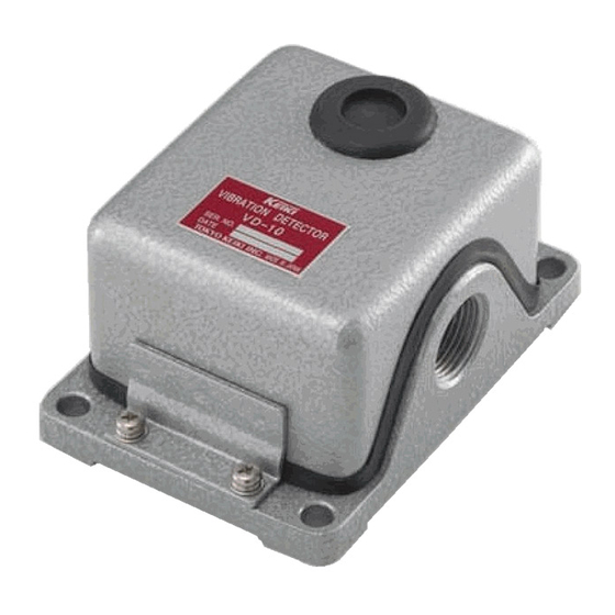
- Page 15 4-φ9 Mounting hole Reset button Gasket (EPR) Conduit hole Fig.2 Outline of the VD-10...
- Page 16 [Blank page]...
-
Page 17: Installation
See the section 1. PRECAUTION and 2. INTRODUCTION Fitting As illustrated in Fig.1, the VD-10 is operated against the acceleration in the vertical direction to the fitting plate surface. Therefore, in the case of general rotating machines, it must be fitted in such a way that the fitting plate surface is vertical to the radial direction of the shaft. -
Page 18: Connection For The Remote Reset Function
Connection for the Remote reset function Instead of manually resetting the VD-10, it is possible to reset it remotely. At the terminal #1 and #2, connect a power source and a switch in series. AC power source and DC power source are available for the power source. -
Page 19: Adjustment
7. Adjustment See the section 1. PRECAUTION and 2. INTRODUCTION Outline When the sensitivity adjustment screw of the detector is turned clockwise, the compression force of the spring which acts on the armature will be increased. Therefore, the detector will operate in small acceleration. - Page 20 NORMAL OPERATING POINT. The acceleration of 2.7G is set to the detector. After finishing the setting of acceleration, fix the adjustment knob protection cover of the detector and reset it. Then, connect the wires to the output terminal. Please tighten the cover screw diagonally and with torque 3 N·m.
-
Page 21: Maintenance
If the operation check of the VD-10 is required, strike the place which is separated slightly from the detector with a hammer and check whether or not an alarm is given. When the VD-10 is in need of repair, send it back to our distributor. The assembly of the detector requires jigs for assembly and testing facilities. - Page 22 [Blank page]...
- Page 23 April/2015 / First Edition September/2017 / Second Edition TOKYO KEIKI INC. MEASUREMENT SYSTEMS COMPANY 2-16-46 Minami-kamata, Ohta-ku, Tokyo 144-8551, Japan TEL +81-3-3737-8621 FAX +81-3-3737-8665 Web http://www.tokyo-keiki.co.jp/ Copyright 2015 by TOKYO KEIKI INC. All rights reserved. (Specifications are subject to change without notice.)
Need help?
Do you have a question about the VD-10 and is the answer not in the manual?
Questions and answers