
Summary of Contents for Zero Zone Highlight MERCHANDISER RHZC30
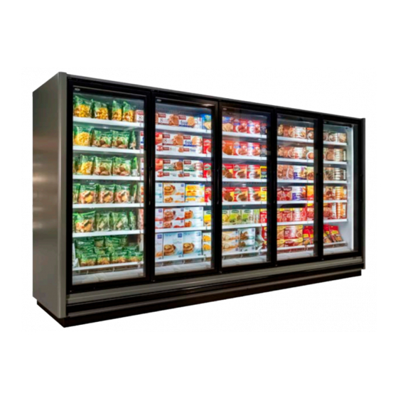
- Page 1 ZERO ZONE HIGHLIGHT MERCHANDISER ® With CoolView Doors & ChillBrite LED Lighting ® ® INSTALLATION & OPERATION MANUAL 66-0032 • MN-18-B • SEP 2019...
-
Page 3: Table Of Contents
Table of Contents ZERO ZONE WARRANTY ..............1 ƒ Electric Defrost - Low Temp ............41 ƒ Limited Warranty ................1 ƒ Hot Gas Defrost - Low Temp ............42 ƒ Extended Warranties ...............1 ƒ Single Point Connection - Low Temp ..........43 ƒ Length of Extended Warranty ............1 ƒ... -
Page 5: Zero Zone Warranty
Zero Zone that the compressor is inoperative due to defects in factory workmanship or material under normal use and services as outlined by Zero Zone in its Installation &... -
Page 6: Introduction
The information in this manual is subject to change without notice and does not represent a commitment on the part of Zero Zone. Zero Zone does not assume any responsibility for any errors that may appear in this manual. In no event will Zero Zone be liable for technical or editorial omissions made herein, nor for direct, indirect, special, incidental, or consequential damages resulting from the use or defect of this manual. - Page 7 INTRODUCTION These display cases were designed and tested using the following industry standards: ASHRAE Standard 72-2014 — Method of Testing Commercial Refrigerators and Freezers (ANSI Approved) ƒ AHRI 1200 — Performance Rating of Commercial Refrigerated Display Merchandisers and Storage Cabinets (ANSI Approved) ƒ...
-
Page 8: Installation & Operation
DAMAGE MUST BE NOTED AT TIME OF DELIVERY AND ALL CLAIMS FOR DAMAGES MUST BE FILED WITH THE TRANSPORTATION COMPANY - NOT WITH Zero Zone. The carrier will supply necessary report and claim forms. -
Page 9: Setting The Case
INSTALLATION & OpERATION If you plan on using optional hat channel rails to raise the case height, place them under each pair of bases. The 3 and 4-door hat channel rails will be angled slightly to support the front and rear bases. See Figure 4 on page 22 See Figure 6I on page Place the required number of shims under each base or optional hat channel rails at each joint (front and back) to equal the highest point. -
Page 10: Lineup Assembly
4 or 5-door cases with 4 1/2" bases. For low shipping height applications, Zero Zone has optional, expandable bases. As shipped, the base is 1 3/4" tall. It is attached with spacers that allow the base to slide away from the bottom of the case to create a gap that allows the use of a 1 1/2"... -
Page 11: Drain Line
Bumper and Kickplate A Zero Zone bumper is standard on all case models and should be installed at the bottom front of the case. Various bumper styles are available. See Figure 17 on page 33. The kickplate assembly is adjustable to compensate for uneven floors. The bumper end cap is factory-installed on bumpers for cases with end panels that do not include Euro trim. -
Page 12: Cleaning
UNDER CASE FLOOR CLEANING (NSF) The floor underneath your Zero Zone display case can be cleaned by following a few simple steps: Remove the fasteners that hold the bottom kick plate to the display case. The fasteners are accessed from the front of the unit. -
Page 13: Shelves
Shelves Zero Zone manufactures many different styles of shelves, baskets, and product stops. The fully assembled shelves are installed in cases prior to shipping. The bottom wire racks and baskets are placed on the shelves for shipping. Solid shelves have three parts: a solid center section and two snap-in brackets. -
Page 14: Service
CONDENSATE EVAPORATION SYSTEM Zero Zone remote cases can be equipped with an automatic condensate evaporation system. The system uses a pump and drain pan located behind the kickplate and a condensate evaporator pan mounted on the top of the case. -
Page 15: Fan Removal
INSTALLATION & OpERATION AIR CURTAIN VELOCITY Air curtain velocity is affected by stocking levels, coil frost loads, temperature, and fan condition. Air velocity should be measured at the back edge of the discharge air honeycomb, at the center of the middle door in the case (other doors have slightly lower velocity). A typical low temp velocity reading is 400 to 500 feet per minute in a fully-packed low temp case, after the case has defrosted and pulled down to operating temperature. -
Page 16: Electrical
After the system has been thoroughly evacuated of all moisture and non condensable gas, charge the system with the proper refrigerant, using “hi-side/low-side” charging techniques. Do not exceed UL low side pressure rating when pressure testing Zero Zone cases. Electrical... - Page 17 INSTALLATION & OpERATION OPTIONAL ELECTRICAL WIRING Single Point Connection (Low Temp) The “single point” connection system is designed to reduce the time required to install and wire one display case with one condensing unit. Figure 29 on page 43. All of the display case controls, including the disconnect switch and the electronic case controls are installed behind the kickplate in the electrical enclosure and prewired.
-
Page 18: Defrosting - Low Temp
Periodic defrosting to keep the coil free of frost is accomplished automatically by a time clock used in conjunction with an electric or hot gas defrost method. For best results, temperature termination of defrost is strongly recommended on Zero Zone cases. DEFROST SETTINGS AND CONTROLS Electric Defrost Frequency: One electric defrost per day is recommended. - Page 19 The RHZC30 and RHZC30T door case has the probe located in the center/bottom of the coil. An adjustable defrost termination thermostat is an available option from Zero Zone. If the case is so equipped, the defrost termination temperature is 50°F. Contractor should verify the 50°F setting.
- Page 20 Sizing and component selection depend on the type of defrost, size, and location of high side refrigeration system. Zero Zone freezers equipped for gas defrost consist of a side port distributor and a TXV check valve for coil defrost, and a suction line check valve to bypass hot gas to the serpentine coil.
- Page 21 INSTALLATION & OpERATION DEFROST HEATER ELEMENT On 30" door cases, one half of the U-shape heater is located on the front of the coil and the other half is located on the rear of the coil. . The electric wire leads are connected in the junction box behind the front kick rail. HEATER ELEMENT REMOVAL Front and Rear Heater Location (RHZC30 and RHZC30T) The U-shape defrost heater has one leg located on the front of the coil and one leg located on the rear of the coil.
-
Page 22: Anti-Sweat Heaters - Low Temp
Remove the front fasteners on the mullion and remove the back plastic of the mullion to access the heater. The case sill heater is located under the front metal strike plate below the door opening. Contact Zero Zone’s Service Department for instructions for servicing this heater. -
Page 23: Illustrations
ILLUSTRATIONS Case Label Information FIGURE 1: CASE LABEL LOCATIONS Refer back to page 4 Illustrations - Case Label Information • 19... -
Page 24: X83; Leveling
ILLUSTRATIONS Leveling FIGURE 2: Leveling Cases Prior to Joining 2A. Measure and mark exact case outline 2B. Mark floor level differences RHZC Shim Placement BB Shim Placement 2C. Shim joints to equal highest point 20 • Illustrations - Leveling Refer back to page 4... - Page 25 ILLUSTRATIONS Leveling FIGURE 3: Positioning Hat Channel Rails Refer back to page 5 Illustrations - Leveling • 21...
- Page 26 ILLUSTRATIONS Leveling FIGURE 4: Typical Rail Locations Hat Channel Rail RELEASED Hat Channel Rail FIGURE 5: Shims Under Bases and Case Case Case Both corners of the base ...
- Page 27 ILLUSTRATIONS Leveling FIGURE 6: Base Locations 6A. 24" 2-Door Case 6B. 24" 3-Door Case 6C. 24" 4-Door Case 6D. 24" 6-Door Case Refer back to page 4 Illustrations - Leveling • 23...
- Page 28 ILLUSTRATIONS Leveling Figure 6: Base Locations (Cont.) 6E. 30" 2-Door Back-to-Back Case 6F. 30" 3-Door Back-to-Back Case 6G. 30" 4-Door Back-to-Back Case 6H. 30" 5-Door Back-to-Back Case 24 • Illustrations - Leveling...
- Page 29 ILLUSTRATIONS Leveling Figure 6: Base Locations (Cont.) 6I. 30" 1-Door Case 6J. 30" 2-Door Case 6K. 30" 3-Door Case 6L. 30" 4-Door Case 6M. 30" 5-Door Case Refer back to page 5 Illustrations - Leveling • 25...
-
Page 30: X83; Moving Cases
ILLUSTRATIONS Moving Cases FIGURE 7: REMOVING WOOD PLANKS FIGURE 8: WOOD BLOCK INSIDE BASE FIGURE 9: EXPANDABLE BASE Spacers 26 • Illustrations - Moving Cases Refer back to page 5... -
Page 31: X83; Rhzc / Rhcc Caulking Instructions
ILLUSTRATIONS RHZC / RHCC Caulking Instructions FIGURE 10 FOLLOWING THIS PROCEDURE IS CRITICAL FOR SEALING JOINED CASES CORRECTLY! 1. Apply one 1/4" to 3/8" wide bead of BUTYL SEALANT to the End Mullion, as shown with dashed lines. Apply two beads at Ceiling, ... -
Page 32: X83; Required Sealing For Nsf-Approved Installations
ILLUSTRATIONS Required Sealing for NSF-Approved Installations FIGURE 11 ... -
Page 33: X83; Joining Insulated Dividers - Rhzc / Rhcc To Rhzc / Rhcc
ILLUSTRATIONS Joining Insulated Dividers - RHZC / RHCC to RHZC / RHCC FIGURE 13 ... -
Page 34: X83; Joining Insulated Dividers - Rhzc / Rhcc To Rvlc / Rvmc
ILLUSTRATIONS Joining Insulated Dividers - RHZC / RHCC to RVLC / RVMC FIGURE 14 ... -
Page 35: X83; Attaching Kickplate Splice - Rhzc / Rhcc To Rvlc / Rvmc
ILLUSTRATIONS Attaching Kickplate Splice - RHZC / RHCC to RVLC / RVMC FIGURE 15 Refer back to page 6 Illustrations - Attaching Kickplate Splice - RHZC / RHCC to RVLC / RVMC •... - Page 36 ILLUSTRATIONS Field-Mounted Trap RELEASED FIGURE 16 Drain Trap Support Drain Support DWG NO.SP-6000-1REV. B 32 • Illustrations - Field-Mounted Trap Refer back to page 7 REVISION INFORMATION REVISION DESCRIPTION DATE ECN No.
- Page 37 THIS DRAWING AND THE INFORMATION CONTAINED WITHIN, IS Illustrations • 33 SP-6002-1 DRAWING No: REVISION CAD DRAWING THE SOLE PROPERTY OF ZERO ZONE, INC. ANY USE OF THIS (UNLESS OTHERWISE SPECIFIED) NO MANUAL REVISIONS DOCUMENT OR DISCLOSURE OF ITS CONTENTS; BY SHEET PART WEIGHT:...
-
Page 38: X83; Under Case Return Air Flow
ILLUSTRATIONS Under Case Return Air Flow FIGURE 19: 34 • Illustrations - Under Case Return Air Flow... -
Page 39: X83; Penetration Sealing
ILLUSTRATIONS Penetration Sealing FIGURE 20: Illustrations - Penetration Sealing • 35 ... -
Page 40: X83; P-Trap Installation
ILLUSTRATIONS P-trap Installation FIGURE 21: 45° ELBOW SUCTION LINE 36 • Illustrations - P-trap Installation... -
Page 41: X83; General
ILLUSTRATIONS General FIGURE 22: TEMPERATURE SETTINGS FROZEN FOOD ICE CREAM MEDIUM TEMP RACK SYSTEMS RACK SYSTEMS RACK SYSTEMS RHZC30 and RHZC30T RHZC30 and RHZC30T RHCC30 and RHCC30T Evaporator temp -7°F Evaporator temp -16°F Evaporator temp +28°F RHCC 24" DOOR Evaporator temp +25°F CONDENSING UNIT CONDENSING UNIT CONDENSING UNIT... -
Page 42: X83; Refrigeration Line Sizing - Low Temp
ILLUSTRATIONS Refrigeration Line Sizing - Frozen Foods FIGURE 24: LOW TEMP - FROZEN FOODS ... - Page 43 ILLUSTRATIONS Refrigeration Line Sizing - Ice Cream FIGURE 25: LOW TEMP - ICE CREAM ...
-
Page 44: X83; Refrigeration Line Sizing - Medium Temp
ILLUSTRATIONS Refrigeration Line Sizing FIGURE 26: REFRIGERATION LINE SIZING ... -
Page 45: X83; Electric Defrost - Low Temp
ILLUSTRATIONS Electric Defrost Wiring FIGURE 27: LOW TEMP Illustrations - Electric Defrost Wiring • 41... -
Page 46: X83; Hot Gas Defrost - Low Temp
ILLUSTRATIONS Hot Gas Defrost Wiring FIGURE 28: LOW TEMP 42 • Illustrations - Hot Gas Defrost Wiring... -
Page 47: X83; Single Point Connection - Low Temp
ILLUSTRATIONS Single Point Connection Wiring FIGURE 29: LOW TEMP Illustrations - Single Point Connection Wiring • 43... -
Page 48: X83; Master/Satellite Wiring - Low Temp
ILLUSTRATIONS Master/Satellite Wiring FIGURE 30: LOW TEMP OPTIONAL CONDENSATE EVAPORATOR 115 V-1-60 DOOR MOUNTED ON TOP OF CASE PLUGGED INTO CONDENSING UNIT SILL ADJUSTABLE DEFROST OR POWERED BY CUSTOMER TERMINATION SET @ 50°F OPEN ON RISE CLOSE ON DROP FANS MULLION USE RED AND BLUE DOT... -
Page 49: X83; Off Cycle Defrost Or Satellite Wiring - Medium Temp
ILLUSTRATIONS Off-Cycle Defrost or Satellite Wiring FIGURE 31: MEDIUM TEMP Illustrations - Off-Cycle Defrost or Satellite Wiring • 45... -
Page 50: Single Point Connection Or Master Wiring - Medium Temp
ILLUSTRATIONS Single Point Connection or Master Wiring - Medium Temp FIGURE 32: SINGLE POINT CONNECTION OR MASTER WIRING 46 • Illustrations - Single Point Connection or Master Wiring - Medium Temp... -
Page 51: Hot Gas Defrost - Low Temp
DWG NO.SP-3000 REV. E LINE REVISION INFORMATION REVISION DESCRIPTION ECN No 9651 Illustrations - Hot Gas Defrost - Low Temp • 47 REVISE BALLOON 14 DEFROST TERMINATION PROBE LOCATION MATERIAL: (NONE) UNLESS OTHERWISE ZERO ZONE, INC. (PER SP-0404) SPECIFIED, ALL DIMENSIONS... -
Page 52: Electric Defrost - Low/Medium Temp
ILLUSTRATIONS Electric Defrost - Low/Medium Temp FIGURE 34: 30" ELECTRIC ITEM # PART NAME 1 COIL COVER 2 FAN 3 LIQUID LINE 4 SUCTION LINE 5 FAN HOUSING 6 HEAT EXCHANGER 7 EXPANSION VALVE *8 HEATING ELEMENT ... - Page 53 Service page at: WWW.ZERO - ZONE.COM or contact the Zero Zone Service Department at: 800-247-4496 All specifications subject to change without notice. ZERO ZONE, INC. • 800-247-4496 • ZERO-ZONE.COM © 2019 Zero Zone, Inc. All Rights Reserved. • SEP 2019 MN-18-B...
Need help?
Do you have a question about the Highlight MERCHANDISER RHZC30 and is the answer not in the manual?
Questions and answers