
Summary of Contents for mfh systems AIRUNIT GEMINI
- Page 1 floor heating AIRUNIT GEMINI systems Decentralised domestic ventilation modern floor heating Installation instructions...
-
Page 2: Table Of Contents
Table of contents Installation instructions page 1. General information ..........................03 2. Function / planning information ......................04 3. Delivery units / scope of delivery ......................05 4. Dimensions / technical data ........................06 5. Selection of the installation location ...................... 6. -
Page 3: General Information
1. General information The AIRUNIT ventilation systems and controller are designed according to the current state of the art and the recognised safety regulations. Installation and maintenance work on the ventilation unit may only be carried out by trained specialists in compliance with the regulations on work safety and accident prevention. -
Page 4: Function / Planning Information
The AIRUNIT GEMINI units must not be used in interior, windowless exhaust air rooms such as kitchens, bathrooms and toilets, as it is not permitted to connect the units to a shaft or pipe. Here the use of an exhaust air fan in accordance with DIN 18017 T.3 is recommended. -
Page 5: Delivery Units / Scope Of Delivery
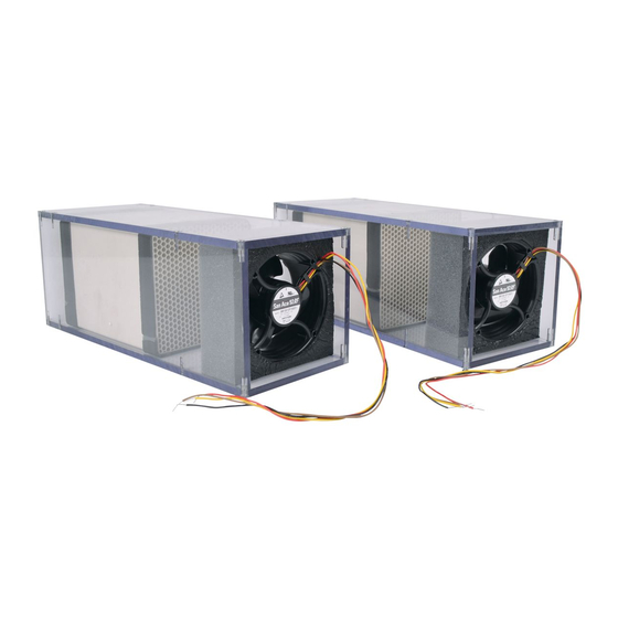
3. Delivery units / scope of delivery A complete AirUnit Gemini ventilation unit consists of a square wall duct with integrated gradient and two ventilator units. The ventilator units each consist of a reversible ventilator (12 V/DC), ceramic heat accumu- lators for heat recovery, the unit electronics, fi lters (ISO Coarse 50% / G3, optional pollen fi lter ePM1 55%) and sealing strips, which are enclosed in a square housing. -
Page 6: Dimensions / Technical Data
4. Dimensions • AIRUNIT GEMINI ventilation unit (all dimension information in mm) 500 (can be shortened to 300) Opening dimension wall breakthrough min. 160 4.1 Technical data AIRUNIT Ventilator unit 5 | 10 | 21 | 30 m³/h in heat recovery mode / Air output 40 m³/h in exhaust air mode... -
Page 7: Selection Of The Installation Location
It is recommended that a minimum distance of 200 mm be main- tained around the wall duct to adjacent facade components / elements and room corners! The AIRUNIT GEMINI devices may not be covered by furniture or curtains. Recommended minimum distance for the Recommended minimum distance for the... - Page 8 6.1 Core drill hole wall duct Prepare two core drillings in diameter ≥ 160 mm, and remove the hatched area to obtain a wall opening of min. 160 x 305 mm (WxH). Alternatively, build the wall duct squarely into the masonry. In both cases, create a cable slot on the upper right edge for the connection cable.
-
Page 9: Electrical Connection
The ventilation units are controlled by 12 V direct voltage (DC), the ventilation units may therefore never be connected to the 230 V mains voltage of the control electronics. As connecting cable for the AIRUNIT GEMINI ventilation units we recommend a cable min. J-Y(ST)Y 2x2x0.6 mm² up to a connection length of 30 metres. Infor-... -
Page 10: Completed Installation
Subsequently, install the wall panel to the weather protection hood using suitable attachment elements. Install the weather protection hood to the AIRUNIT GEMINI ventila- tion unit. The hood is mounted onto the attached lugs on the upper edge of the wall panel and fi xed to the underside of the wall bracket... - Page 11 Mount the console of the design panel with suitable fastening elements with the device electronics facing upwards. Carefully push the ventilator units (ventilator points towards the room) into the wall duct. Make sure that the connecting cable of the ventilator is not bent / damaged in the process.
-
Page 12: Function Check
After switching on the power supply (usually via the circuit breaker of the electrical installation) the AIRUNIT GEMINI can be put into opera- tion via the control panel of the AIRUNIT control unit. When starting up, check all functions described in the operating instructions of the control unit. -
Page 13: Wall Cover Folding Instructions
Wall cover folding instructions... -
Page 14: Commissioning Protocol
systems modern floor heating Commissioning protocol Checklist systems modern floor heating Installation work completely fi nished Electrical connection properly performed / tested Device function checked Filter insert / inserts deployed Instruction of device operator carried out (operation, maintenance) Hand over device documents (installation / operating instructions) •... -
Page 15: Maintenance Log
systems modern floor heating Maintenance log Maintenance work: Executed by: systems modern floor heating... -
Page 16: Erp Data Sheet
floor heating AIRUNIT – Decentralised domestic ventilation ErP data sheet Description Values systems Supplier mfh systems GmbH modern floor heating Model identification AIRUNIT GEMINI cold -82,5 SEV class / average -41,1 Specific energy consumption warm -17,3 Living space ventilation system... -
Page 17: Ec Declaration Of Conformity
floor heating EC Declaration of Conformity Ventilation unit systems Hersteller Manufacturer mfh systems GmbH modern floor heating Hager Feld 8 49191 Belm Germany The undersigned hereby certifi es that the following device(s) complies/comply with the applicable EU directives. This certifi cation loses its validity if the device(s) is/are modifi ed. -
Page 18: Notes
Notes...
Need help?
Do you have a question about the AIRUNIT GEMINI and is the answer not in the manual?
Questions and answers