Table of Contents
Advertisement
Quick Links
This owner's manual was as current as possible when this product was manufactured. However,
products are constantly being updated and improved. Because of this, some differences may occur
between the description in this manual and the product you received.
MODEL 1805B
RF Control Unit
Instruction Manual
P/N IM200-CD
Rev. J
TEGAM, INC.
TEN TEGAM WAY
GENEVA, OH 44041
TEL: (440) 466-6100
FAX: (440) 466-6110
www.tegam.com
Publication Date: January 2014
Advertisement
Table of Contents

Summary of Contents for Tegam 1805B
- Page 1 MODEL 1805B RF Control Unit Instruction Manual P/N IM200-CD Rev. J This owner’s manual was as current as possible when this product was manufactured. However, products are constantly being updated and improved. Because of this, some differences may occur between the description in this manual and the product you received.
- Page 2 SAFETY SUMMARY DEFINITIONS The following definitions apply to WARNINGS, CAUTIONS, and NOTES found throughout this manual. WARNING Highlights an operating or maintenance procedure, practice, statement, condition, etc., which, if not strictly observed, could result in injury and/or death of personnel. Do not proceed beyond a WARNING symbol until all the indicated conditions have been fully understood and/or met.
-
Page 3: Detailed Precautions
Using these items will cause extensive damage to the instrument surface. NOTE DO NOT return any instrument or component to TEGAM without receiving prior factory authorization. SAFETY SYMBOLS The following symbols are used to identify safety hazards found throughout this publication and/or located on the instrument. -
Page 4: Table Of Contents
INTRODUCTION AND GENERAL DESCRIPTION INTRODUCTION.......................... 1-1 Purpose.......................... . 1-1 Scope ..........................1-1 Arrangement........................1-1 Related Manuals.......................1-1 Contacting TEGAM......................1-2 Electrostatic Discharge Sensitive..................1-2 Abbreviations and Acronyms..................... 1 -3 Safety Considerations.......................1-3 GENERAL DESCRIPTION......................1-3 Description of Equipment....................1-3 Functional Description....................1-3 Physical Description....................1-3... - Page 5 Line Voltage and Fuse Selection..................2-5 PREPARATION FOR RESHIPMENT OR STORAGE ..............2-8 Reshipment........................2-8 Storage..........................2-9 SECTION III THEORY AND OPERATION GENERAL ..........................3-1 OPERATION ..........................3-1 GENERAL OPERATING CONSIDERATIONS................3-2 CONTROLS AND INDICATORS ....................3-2 LISTEN Indicator......................3-3 REMOTE Indicator......................3-3 STANDBY Indicator......................3-3 POWER Switch........................
-
Page 6: List Of Illustrations
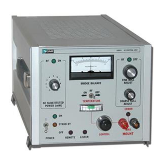
System IIA Closed Loop Stability Test................4-6 CONTACTING TEGAM........................4-9 WARRANTY........................... 4-9 List of Illustrations RF Control Unit, Model 1805B ..................... 1-1 Model 1805B Assembly Location....................1-4 Typical Configuration........................1-6 10 mW Configuration Using Model 1727A..................1-8 SWR Measurement Configuration ....................1-8 75 Ohm Sensor Calibration Setup.................... - Page 7 Address Switch ........................3 - 5 Simplified Microprocessor Block Diagram............... 3 - 9 Precision Power Source Schematic................3-10 RF Amplifier Functional Diagram..................3-11 Temperature Control Circuitry..................3 -11 Simplified dc Substitution Circuitry................. 3 -13 Closed Loop Stability Test....................4 -6 Removal and Installation ....................4-7 LIST OF TABLES Specifications ........................
-
Page 8: Introduction And General Description
PURPOSE This manual provides Operation and Service instructions necessary to install, service, test, and operate the TEGAM Model 1805B RF Control Unit (P/N 138-415-1). SCOPE This manual is to be used in conjunction with the operation and maintenance of the RF Control Unit. -
Page 9: Contacting Tegam
Model 1727A, Amplifier, Operation and Service Manual CONTACTING TEGAM In the event of an instrument malfunction, contact TEGAM. An apparent malfunction of an instrument or component may be corrected over the phone by contacting TEGAM. DO NOT send the instrument or component back to the factory without prior authoriza- tion. -
Page 10: Abbreviations And Acronyms
• Internal temperature controller for controlling internal temperature of thermistor mount. Physical Description Refer to Table 1 -1 for all the physical dimensions for the RF Control Unit, Model 1805B. The RF Control Unit features a POWER ON/OFF/STANDBY switch/indicators, a... -
Page 11: Specifications
REAR PANEL ASSEMBLY RF CABLE ASSEMBLY RF CABLE ASSEMBLY ADDRESS SWITCH CABLE ASSEMBLY CABLE BAND SELECT ASSEMBLY INPUT POWER ASSEMBLY Specifications Table 1-1 lists specifications to be considered when using the RF Control Unit. Figure 1-2 Model 1805B Assembly Location... -
Page 12: Recommended Materials
All recommended special tools and test equipment to be used with the RF Control Unit are listed in Table 1-3. APPLICATIONS The primary function of the Model 1805B is to function as part of the TEGAM System IIA Precision Power Source for the transfer of calibration factors to power meter sensors. Figure... - Page 13 GHz frequency range. Refer to the Model 1727A Operation and Service Manual for more information. Figure 1-5 shows a setup to using the Model 1805B as part of the System IIA Precision Power source and the TEGAM SWR Measurement Kit to measure Return Loss/SWR. The SWR Measurement Kit includes a return loss bridge with an "open"...
-
Page 14: Special Tools And Test Equipment
Operation & Service Manual Section I Model 1805B RF Control Unit Introduction and General Description Table 1-2 Recommended Consumable Materials Acid Brush (Fiber Bristle) H-B-643 Type II CLASS Aluminum Wool MIL-A-4864A Brush, Soft Bristle H-B-420 Type II Cleaner/Solvent Isopropyl Alcohol... - Page 15 Operation & Service Manual Section I Model 1805B RF Control Unit Introduction and General Description Figure 1-4 10 mW Configuration Using Model 1727A Figure 1-5 SWR Measurement Configuration...
- Page 16 Model 1805B RF Control Unit Introduction and General Description Figure 1-6 shows a setup to using the Model 1805B as part of the System IIA Precision Power source and the TEGAM 50-75 Ohm Minimum Loss Matching Pad (PN 138-650) to calibrate 75 ohm power sensors over the 0.1 MHz-2.7 GHz frequency range.
- Page 17 Operation & Service Manual Section I Model 1805B RF Control Unit Introduction and General Description Figure 1-8 Spectrum Analyzer Calibration Setup 1-10...
- Page 18 Operation & Service Manual Section I Model 1805B RF Control Unit Introduction and General Description Figure 1-9 Model 1805B Physical Dimensions 1-11...
- Page 19 Operation & Service Manual Section I Model 1805B RF Control Unit Introduction and General Description 1-12...
-
Page 20: Installation And Shipment
Refer to Initial Setup (below) before applying any power to the instrument. ENVIRONMENTAL REQUIREMENTS The Model 1805B operates best within its specifications at an ambient temperature of +10° to +40°C. Operating beyond these limits can affect the accuracy of the instrument and damage internal circuitry. -
Page 21: Preparation For Use
The RF Control Unit is shipped with four plastic feet mounted to the bottom cover. This allows the user to place the instrument on any bench or to stack the Model 1805B with other TEGAM instruments. When the instrument is placed on a bench or table, these feet provide a level support. -
Page 22: Mount Bias (+/-) Terminals (E1 And E2)
Model 1805B RF Control Unit Installation and Shipment Sufficient power levels are present at the Power Input Assembly to cause personal injury. Ensure that the Model 1805B power cord is DISCONNECTED before attempting to change fuses. Figure 2-2 Model 1805B Connector Location (Front) -
Page 23: Ieee-488 Interface Bus (J3)
Figure 2-3 Model 1805B Connector Location (REAR) IEEE-488 INTERFACE BUS (J3) Joining the Model 1805B to a system controller requires the connection of IEEE-488 control bus to the IEEE-488 INTERFACE BUS connector located on the rear panel (Figure 2-3). The IEEE-488 INTERFACE BUS connector carriers program command and data signals passing between the RF Control Unit and a system controller. -
Page 24: Line Voltage And Fuse Selection
GND, LOGIC LINE VOLTAGE AND FUSE SELECTION When shipping with the U.S., TEGAM configures the 1805B for 120-Volt operation. Overseas shipments may vary. The following steps provide procedures to reconfigure the line voltage and replace the Fuse Assembly (Figure 2-5). Table 2-2 lists fuse requirements for the available operational voltages. - Page 25 Operation & Service Manual Section II Model 1805B RF Control Unit Installation and Shipment d. Position the Voltage Selector PC Board so that the desired voltage appears readable (right-side-up) on the left-hand side of the wafer as it faces you. The “X” on the board in the diagram depicts this location.
-
Page 26: Precision Power Source Setup
Operation & Service Manual Section II Model 1805B RF Control Unit Installation and Shipment *Models 1109, 1109H, 1116, 1117A, 1119H or 1119 Figure 2-6 Precision Power Source Setup... -
Page 27: Preparation For Reshipment Or Storage
Figure 2- 7 Precision Power Source Setup PREPARATION FOR RESHIPMENT OR STORAGE RESHIPMENT Perform the following procedures when reshipping an instrument or component: NOTE • DO NOT return any instrument or component to TEGAM without receiving prior factory authorization (RMA Number). -
Page 28: Storage
TEN TEGAM WAY GENEVA, OH 44041 USA STORAGE When Model 1805B is to be stored for extended periods, pack instrument into a container using procedure described above. Place container into a clean, dry, temperature-controlled location. If instrument is to stored in excess of 90 days, place desiccant with items before sealing container. -
Page 29: General
This ensures full performance capability and long term stability of the bolometer mount. The Model 1805B provides automatic dc level control to within ± 0.1 %, +1 μW, with an RF source variation of ±3 dB and an ambient temperature range of +10 to +40°C. The dc substitution level is held to an accuracy of +0.1%, +5 μW. -
Page 30: General Operating Considerations
When operated from a cold start, the RF Transfer Standard used with the Model 1805B will require at least two hours to reach temperature stability under control of a temperature controller. -
Page 31: Listen Indicator
LISTEN INDICATOR. The LISTEN indicator (DS6) is a red LED located in the bottom center of the front panel. This indicator is only illuminated when the Model 1805B is addressed as a listener via the IEEE- 488 bus. REMOTE INDICATOR The REMOTE indicator (DS7) is a red LED located in the bottom center of the front panel. -
Page 32: Rf Off Indicator
30 mW dc power is supplied to the mount, and the appropriate RF control signal is routed to the rear panel. If the 1805B is under remote IEEE-488 bus control, DS1 illuminates when the functions of RF OFF (0) have been performed by the automatic system controller. -
Page 33: Operating Instructions
ON position is selected, a red band appears in the ON position. OPERATING INSTRUCTIONS The Model 1805B RF Control Unit was primarily designed as one component of the TEGAM System IIA whose purpose is to accurately transfer the calibration factors of NIST standards to feedthrough and terminating bolometer mounts, thermistor mounts, and power sensors. -
Page 34: Manual Operation
1805B removed for troubleshooting. f. After the system has had the additional 1/2 hour of warm-up with the POWER switch in the ON position, and if all indications are normal (as outlined above), the 1805B is ready for operation. MANUAL OPERATION... -
Page 35: Remote Operation
IEEE Standard 488-1978, "Digital Interface for Programming Instrumentation." The REMOTE indicator is lit when the 1805B is placed into remote mode by the bus controller. When the 1805B is addressed by the bus controller, the LISTEN indicator illuminates and stays lit until another device on the bus is addressed. -
Page 36: Terminating Operation
Wheatstone bridge circuit, which origi nates in the TEGAM Model 1805B RF Control Unit. When a precise level ofdc bias is removed from this bridge circuit by manual or bus-controlled switching of the Model 1805B, an unbalance bridge condition occurs. -
Page 37: Microprocessor Section
Due to the continual scanning of the microprocessor, detection of any front panel function change occurs unless the 1805B is set to remote mode in which case the microprocessor switches to a new set of instructions. -
Page 38: Precision Power Source Schematic
U3 is a microprocessor-controlled with eight read and eight write registers that interfaces the Model 1805B to an IEEE-488 interface bus via two operation, i.e., the processor outputs the correct bits to the driver chips to implement the required function. -
Page 39: Rf Amplifier Section
Operation & Service Manual Section III Model 1805B RF Control Unit Theory & Operation Since the microprocessor is scanning U3, the front panel is deactivated. Therefore, switching front panel controls does not cause a functional change by the unit. Once in the remote mode U3 handles all bus protocol. -
Page 40: Bridge Offset Sensing Circuit
Wheatstone bridge imbalance. This circuit gives the 1805B the required gain to achieve the high sensitivity to the level ofdc bias substituted for RF levels. Three operational amplifiers make up this circuit. U6 senses the bridge differential and provides high gain, U7 conditions signals, and U8 drives the RF generator AM Modulation signal (via board connector J4 and rear panel connector J2 ). -
Page 41: Calibration
If the thermistor fails to bias within .7 mW of the 30 mW bias point, the front panel indicator illuminates. CALIBRATION The following paragraphs provide theory used to perform calibration on the Model 1805B and its associated thermistor mount. DC SUBSTITUTION A calibration system, such as the TEGAM System IIA, utilizes the principle ofdc substitution. - Page 42 Operation & Service Manual Section III Model 1805B RF Control Unit Theory & Operation 3-14...
- Page 43 Operation & Service Manual Section III Model 1805B RF Control Unit Theory & Operation Note that with active devices such as spectrum analyzers, no absolute accuracy device or system is used e.g. dc substitution, thermistors etc., so that uncalibrated power measurement values can be quite arbitrary.
-
Page 44: General
PREVENTIVE MAINTENANCE While the Model 1805B RF Control Unit requires very little preventive maintenance, it should not be subjected to physical abuse, severe mechanical shock, high humidity, or operating temperatures outside the specification range. The instrument should be kept free of excessive dirt end dust, since these can interfere with connector functions and with normal heat dissipation. -
Page 45: Machined Surfaces And Hardware
Operation & Service Manual Section IV Model 1805B RF Control Unit Testing CAUTION • Do NOT use a nylon bristle brush in the solvent as the bristles may dissolve and cause damage to the circuit card or component. • Do NOT use ultrasonic cleaning on parts or assemblies containing electrical or electronic components. -
Page 46: Chassis Cleaning
Operation & Service Manual Section IV Model 1805B RF Control Unit Testing Table 4-1 Inspection ITEM INSPECTION Capacitors Cracked, blistered, or dented; broken or loose seals or leads; signs of leakage (polarized tantalum capacitors); loose or missing mountings. Castings, Housings Dents, cracks, scratches, or other damage;... -
Page 47: Performance Testing
(J1) to the 1805B Temperature CONTROL connector (J1) via a temperature control cable (P/N 138-477). c. Set 1805B RF ON/OFF switch (S2), located in the center of the front panel, to the OFF position. d. Turn 1805B POWER switch (S1), located on the bottom left side of the front panel, to the STANDBY and ON positions ensuring that the proper LED’s (DS5 or DS4) illuminate. -
Page 48: Bias Power Range Test
Section IV Model 1805B RF Control Unit Testing a. Obtain a reading of 1.22474 V ±10 mV (E I )on the DVM by adjusting the 1805B FINE NULL ADJUST (R1) and COARSE NULL ADJUST (R2) knobs on the right front panel. -
Page 49: Temperature Control Circuit Verification
TEMPERATURE Control Meter (M2) located on the lower center of the front panel. When a cold thermistor mount is first connected to the 1805B and the 1805B is in POWER STANDBY mode, the needle of the TEMPERATURE Control Meter should provide an approximate full- scale reading (9.2 to 10.2). - Page 50 Operation & Service Manual Section IV Model 1805B RF Control Unit Testing MODEL NOMENCLATURE PC Controller with National Instruments IEEE-488 (GPIB) interface Windows Compatible Printer TEGAM SYSIIA-Surecal Surecal Windows ™ Software TEGAM 1109/ Feedthrough Thermistor Mount 1807A/1116/1117A/1119 Synthesized CW Signal Source, +10 dBm, 0.01-18 GHz*...
-
Page 51: Contacting Tegam
Set the Signal generator to a desired frequency. For example, if using a F 1109, select a frequency between 0.01 and 18 GHz. e. Set the dc substituted power level of the Model 1805B according to the value of P in Table 4-2. - Page 52 TEGAM, Inc. warrants the calibration of this product for a period of one year from date of shipment. During this period we will recalibrate any product that does not conform to be published accuracy specification.
-
Page 53: Care And Handling Of Microwave Coaxial Cable Assemblies
Also inspect the mating connectors for similar damage. Table A -1 provides both TEGAM specifications and MIL-C39012C data for the pin height of the various types of connectors. Pin height is defined as the vectorial distance along a horizontal axis of the pin shoulder from the electrical/mechanical reference plane. -
Page 54: Making Initial Connections
APPENDIX A CARE AND HANDLING OF MICROWAVE COAXIAL ASSEMBLIES If signs of debris are present, clean the connector interface as directed below in Cleaning Connector Interfaces. MAKING INITIAL CONNECTIONS Exercise caution when mating cables. Poor connections lead to poor system performance. They can also damage not only the cable assembly, but more significantly, front or rear panel connectors on the equipment itself which may be more difficult to repair. - Page 55 APPENDIX A CARE AND HANDLING OF MICROWAVE COAXIAL ASSEMBLIES Figure A-2 Important Interface Dimensions for Type 7 MM, Precision Connectors (IEEE Std 287) FIGURE A-3. IMPORTANT INTERFACE DIMENSIONS FOR TYPE BNC, CLASS II CONNECTORS (MIL-C-39012/16 & 17)
-
Page 56: Mating Connectors
APPENDIX A CARE AND HANDLING OF MICROWAVE COAXIAL ASSEMBLIES Figure A-4 Important Interface Dimensions for Type BNC, Class II Connectors (MIL-C- 39012/16&17) Figure A-5 Important Interface Dimensions for Type TNC, Class II Connectors (MIL-C- 39012/26&27) MATING CONNECTORS Gently mate the connectors by hand, taking care not to force the coupling nut at the slightest resistance. -
Page 57: Ensuring Proper Connector Torque
APPENDIX A CARE AND HANDLING OF MICROWAVE COAXIAL ASSEMBLIES difficult to turn, either the pins are not mated, the coupling nut is cross-threaded, or one of the connectors has been damaged by excess torque. Never hold a male connector coupling nut stationary while screwing a female connector into it. This rotation can erode the plating and damage both the outer interface rim as well as the pin. -
Page 58: Securing Cables
APPENDIX A CARE AND HANDLING OF MICROWAVE COAXIAL ASSEMBLIES Never pinch, crush or drop objects on cable assemblies. Also, do not drag a cable over sharp edges as this will pinch it and cause it to exceed the minimum bend radius. Never use a cable assembly to pull a piece of equipment.
Need help?
Do you have a question about the 1805B and is the answer not in the manual?
Questions and answers