
Subscribe to Our Youtube Channel
Related Manuals for Ormazabal velatia mb.m Series


Summary of Contents for Ormazabal velatia mb.m Series
- Page 1 mb.m Outdoor metal prefabricated transformer substation General Instructions IG-245-EN, version 05, 13/02/2020...
- Page 2 Therefore, the use of this equipment poses electrical, mechanical and thermal risks. In order to ensure an acceptable level of protection for people and property, and in compliance with applicable environmental recommendations, Ormazabal designs and manufactures its products according to the principle of integrated safety, based on the following criteria: •...
-
Page 3: Table Of Contents
General Instructions Contents mb.m Contents 1. Description and main characteristics .......4 5. Installation ...............22 Elements of the mb.m ..... . . 4 1.1. -
Page 4: Description And Main Characteristics
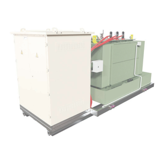
Description and main characteristics General Instructions mb.m Description and main characteristics Ormazabal's mb.m transformer substation is a frame- mb.m is designed for installations in electrical networks mounted prefabricated metal transformer substation, with rated voltage up to 40.5 kV in alternating current. Its... - Page 5 General Instructions Description and main characteristics mb.m Other available options are: • IP1X perimeter protection for the transformer unit. • Oil collection tank with incorporated valve and lter. • Low voltage cable bracket. • Medium voltage cable bracket (clamp with maximum diameter 95 mm and minimum diameter 48 mm).
-
Page 6: Medium Voltage Switchgear
It has up to three one-core cable inputs, with a maximum diameter of 50 mm. For other types of cables, please contact Ormazabal. IG-245-EN version 05; 13/02/2020... -
Page 7: Power Transformer
4 MVA in the case of mb.m with low voltage outputs. Approximate maximum power for Ormazabal transformers, in accordance with the weight, dielectric volume and maximum admissible dimensions of the transformer set out in chapter “Mechanical ratings” of this document. -
Page 8: Name Plate
Table 1.2. Weight of mb.m < 2500 kVA in accordance with cubicle con guration Weights valid for 2000 kVA transformer weighing 5000 kg. Check with Ormazabal for transformers with other powers. Not including the weight of optional elements such as: - Perimeter fence (additional weight: 110 kg). -
Page 9: Dimensions And Weight Of Mb.m For Transformer Power Equal To Or Above
Table 1.4. Weight of mb.m ≥ 2500 kVA in accordance with cubicle con guration Weights valid for 3000 kVA transformer weighing 6270 kg. Check with Ormazabal for transformers with other powers. Not including the weight of optional elements such as: - Perimeter fence (additional weight: 150 kg) - Dielectric uid tank (additional weight: 236 kg). -
Page 10: Dimensions And Weight Of Mb.m With Low
Table 1.6. Weight of mb.m with low voltage outputs in accordance with cubicle con guration Weights valid for 3000 kVA transformer weighing 6270 kg. Check with Ormazabal for transformers with other powers. Not including the weight of optional elements such as: - Perimeter fence (additional weight: 150 kg) - Dielectric uid tank (additional weight: 205 kg). - Page 11 General Instructions Description and main characteristics mb.m Figure 1.4. Dimensions of mb.m-3f with transformer < 2500 kVA (in mm) IG-245-EN version 05; 13/02/2020...
- Page 12 Description and main characteristics General Instructions mb.m Figure 1.5. Dimensions of mb.m-4f with transformer < 2500 kVA (in mm) IG-245-EN version 05; 13/02/2020...
- Page 13 General Instructions Description and main characteristics mb.m Figure 1.6. Dimensions of mb.m-3f with transformer ≥ 2500 kVA (in mm) IG-245-EN version 05; 13/02/2020...
- Page 14 Description and main characteristics General Instructions mb.m Figure 1.7. Dimensions of mb.m-4f with transformer ≥ 2500 kVA (in mm) IG-245-EN version 05; 13/02/2020...
- Page 15 General Instructions Description and main characteristics mb.m Figure 1.8. mb.m-3f dimensions with low voltage outputs (in mm) IG-245-EN version 05; 13/02/2020...
- Page 16 Description and main characteristics General Instructions mb.m Figure 1.9. mb.m-4f dimensions with low voltage outputs (in mm) IG-245-EN version 05; 13/02/2020...
-
Page 17: Transport
General Instructions Transport mb.m Transport 2.1. Location of accessories during transport mb.m is supplied with the following components: Ormazabal General Instructions document IG-245. • • Manual operating lever for the driving mechanisms of the medium voltage cubicles. • Cubicle control diagram. -
Page 18: Selecting The Route For Road Transport
Checking impact detectors Ormazabal reserves the right to t impact detectors (or If transport is not managed by Ormazabal, or is not carried ask for them to be tted) in its transformers, in order to out under its responsibility, and accelerations in excess... -
Page 19: Sea Transport
Recommendations for HC transport. For other types of sea transport, please contact The maximum dimensions of the mb.m are 2296 mm wide Ormazabal. and 2527 mm high. For correct transport of the mb.m, the four 200 mm-diameter wheels should be tightened... -
Page 20: Storage
Do not store in corrosive, saline or aggressive environments. Check with Ormazabal when stored for over 3 months. When the mb.m is stored outdoors and includes an oil lter, its shut-o valve should be opened. Follow the instructions set out in point 7 for maintenance. -
Page 21: Normal Service Conditions
50% at a maximum temperature of 40 ºC. event of special conditions of use, please check with Higher degrees of relative humidity are permitted at Ormazabal. lower temperatures. Moderate condensation may occasionally occur due to temperature variations. IG-245-EN version 05; 13/02/2020... -
Page 22: Installation
Installation General Instructions mb.m Installation When installing the mb.m in its location, it is essential operation, taking into account the distances to overhead to comply with the applicable standards for electrical lines, slopes, etc. installations in electrical networks, in addition to local These protection measures, in addition to the wheels legislation. -
Page 23: Planning
A table is attached showing the recommended values for the di erent crane powers, remembering that these are provided as a guide and each individual case should be con rmed with Ormazabal. Figure 5.1. O oad operation MAXIMUM DISTANCE "D" FOR CRANE-TRUCK MAXIMUM DISTANCE "D"... -
Page 24: Preparing The Ground
General Instructions mb.m 5.3. Preparing the ground Ormazabal recommends installing the mb.m on a 300 mm- thick reinforced concrete slab with a 100 x 100 mm wire mesh, 8 mm in diameter. A ± 2 mm smooth, level uniform concrete slab nish is recommended. - Page 25 This drawing and the dimensions shown are merely Make sure the supporting slab is correctly levelled for the purposes of illustration. The project's detailed before placing the mb.m on it. drawings will take precedence. For further information, please contact Ormazabal. IG-245-EN version 05; 13/02/2020...
- Page 26 This drawing and the dimensions shown are merely Make sure the supporting slab is correctly levelled for the purposes of illustration. The project's detailed before placing the mb.m on it drawings will take precedence. For further information, please contact Ormazabal. IG-245-EN version 05; 13/02/2020...
- Page 27 This drawing and the dimensions shown are merely Make sure the supporting slab is correctly levelled for the purposes of illustration. The project's detailed before placing the mb.m on it drawings will take precedence. For further information, please contact Ormazabal. IG-245-EN version 05; 13/02/2020...
-
Page 28: Handling
Ormazabal recommends the lifting beam should be at least 2320 mm long, in order to ensure the chains or slings do not interfere with the unit. The chains or slings must be at least 3 m long. -
Page 29: Removing From An Hc-Type Sea Container
General Instructions Installation mb.m 5.4.2. Removing from an HC-type sea container 1. Remove and set aside the boxes supplied inside the sea container, which include material to be used in subsequent operations. 2. Remove all elements used to fasten the mb.m to the container (stoppers anchored to the container oor, slings, chains, etc.). - Page 30 Installation General Instructions mb.m 4. Following the instructions and recommendations in chapter 5.4.1, place the lifting tools in the two lifting eyebolts and continue to remove the mb.m using the pallet truck and the crane; continue until the two anchor points of the remaining lifting eyebolts become accessible.
- Page 31 General Instructions Installation mb.m 7. Once the mb.m is outside the container, remove the four wheels. Slightly raise the mb.m for suitable access to the frame area. Tool: 24 mm open-end wrench. Risk of crushing: do not remain under the mb.m during handling operations.
-
Page 32: Cable Access And Sealing
Figure 5.13. E ective space of the cable holes in the concrete Please check with Ormazabal. slab – mb.m-3f with transformer < 2500 kVA Figure 5.14. E ective space of the cable holes in the concrete slab –... - Page 33 General Instructions Installation mb.m Figure 5.15. E ective space of the cable holes in the concrete Figure 5.17. E ective space of the cable holes in the concrete slab – mb.m-3f with transformer ≥ 2500 kVA slab – mb.m-3f with low voltage outputs Figure 5.16.
-
Page 34: Door Adjustment
Installation General Instructions mb.m 5.6. Door adjustment Proceed as follows if the doors are not square once installation is complete: 1. Turn the M16 bolt left or right, depending on the leaf to be adjusted, until the door is correctly levelled (see Figure 5.19). -
Page 35: Earthing Circuit Connection
General Instructions Installation mb.m 5.7. Earthing circuit connection The mb.m transformer substation has an earthing bar to protect all the components of the prefabricated substation: The metal frame of the mb.m. • The metal frame of the mb.m has an earthing bar for M10, which the facility's earth must be connected to. -
Page 36: Replacing The Electrical Equipment
Installation General Instructions mb.m 5.8. Replacing the electrical equipment 5.8.1. Replacing the medium voltage switchgear Proceed as follows to replace the electrical equipment installed in mb.m: • Remove the power supply in the medium and low voltage connections to the mb.m transformer substation, where present. -
Page 37: Replacing The Transformer Unit
General Instructions Installation mb.m 5.8.2. Replacing the transformer unit • Remove the medium voltage cable connections and If the transformer unit is tted with perimeter the transformer low voltage outputs as indicated in the protection and other accessories (e.g. terminal relevant general instructions. - Page 38 Installation General Instructions mb.m Follow the procedure: 1. Disconnect all the earth conductors, repeating the following sequence in each equipotential connection: a. Remove the screws that connect the earth conductor terminals to the fence's electrowelded point. Tool: two 10 mm open-end wrenches. Figure 5.24.
-
Page 39: Transformer Secondary Connection
General Instructions Installation mb.m b. Unscrew the two bolts that join the two halves of the clamp. Tool: Phillips screwdriver. Figure 5.26. Disassembling the clamp's connecting bolts c. Separate the clamp to release the panel. d. Repeat the process for all clamps that hold the panel to be taken down. -
Page 40: Recommended Sequence Of Operations
Recommended sequence of operations General Instructions mb.m Recommended sequence of operations All operations and accesses recommended in this It is essential to comply with the sequence of operations speci cation must comply with the procedures indicated set out in the general instructions of the medium voltage by the utility company, and the electrical safety regulations cubicles and transformer equipment. -
Page 41: Annex: Recommended Tightening Torques
General Instructions Annex: recommended tightening torques mb.m Annex: recommended tightening torques The recommended torques for the electrical joints are as follows: Metric size Wrench size Low voltage (LV) Connection between nuts 15-20 70-100 250-300 Fastening the palms to the pin (stainless steel bolts) 25-35 40-60 Bolts at palm surface... - Page 42 Notes General Instructions mb.m Notes IG-245-EN version 05; 13/02/2020...
- Page 44 Subject to change Prefabricados Uniblok without prior notice. For further information, SESEÑA please contact Spain Ormazabal. www.ormazabal.com...
Need help?
Do you have a question about the velatia mb.m Series and is the answer not in the manual?
Questions and answers