
Summary of Contents for Orbit Merret OMR 700 Series
- Page 1 USER GUIDE OMR 700 148. 9 ~C -263mm PAPERLESS RECORDER 453mV Outstanding Measurement Value...
- Page 2 The recorder is not designed for installation in potentially explosive surroundings (Ex). Use it only outside potentially explosive surroundings. TECHNICAL DATA Paperless recorders of the OMR 700 series conform to the Europen regulations 2014/30/EU and 2014/30/EU. They are up to the following European and Czech standards: EN 61010-1, Electrical safety EN 61326-1, Electronic measuring, control and laboratory devices - Requirements for EMC „Industrial use“...
-
Page 3: Table Of Contents
148. 9 ~C -263mm CONTENTS 1. 453mV 1. CONTENTS ......3 2. -
Page 4: Description Of The Instrument
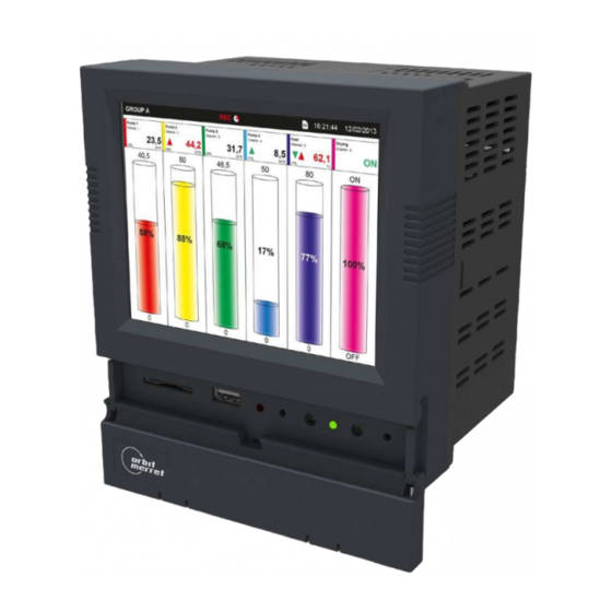
DESCRIPTION OF THE INSTRUMENT DESCRIPTION Paperless recorder OMR 700 This recorder is intended for technologies and workings, where it is needed to display and/or record a number of electrical and nonelectrical values at one place. Universality, versatility and in particular good value for money predestine the recorder to fulfil most of your demanding needs including the IP64 front panel cover. - Page 5 148. 9 ~C -263mm DESCRIPTION OF THE INSTRUMENT 453mV Modules The development of the device has been performed with an increased emphasis on technical solutions and universality. Card design not only allows their use in any position of the recorder, but also their additional insertion into vacant slots.
-
Page 6: Connection Of The Instrument
CONNECTION OF THE INSTRUMENT Supply lines of the instrument should not be situated in proximity of the incoming low-voltage signals. Contactors, motors with larger input power and other power elements should not be situated close to the recorder. Supply lines to the instrument input (measured quantity) should be situated at a sufficient distance from all power lines and appliances. -
Page 7: Card Connection
148. 9 ~C -263mm CONNECTION OF THE INSTRUMENT 453mV IN.1 3x Universal input IN.2 4x PM input U-I IN.01 IN.02 DC - I: ±5/±20 mA, 0...20/4...20 mA DC - U: ±2/±5/±10/±40 V, 0...2/5/10/40 V DU: Lin. potentiometer (> 500 Ω) PM: 0…5/20 mA/4…20 mA OHM: 0…0,1/0,3/1/3/10/30 kΩ... - Page 8 CONNECTION OF THE INSTRUMENT IN.7 12x DC input, voltage IN.8 2x input for strain gauges IN.07 IN.08 - - - - - - DC - U: 0…2 V/0…5 V/0…10 V/0…40 V/±2/±5/±10/40 V DMS: 1…16 mV/V IN.9 3x PM input U-I IN.10 2x AC/PWR input IN.09...
- Page 9 148. 9 ~C -263mm CONNECTION OF THE INSTRUMENT 453mV IN.13 2x Fast pulse input IN.14 2x input for LVDT sensors IN.13 IN.14 contact 3-wire sensors, PNP NO 3-wire LVDT sensors 2-wire sensors, NPN NO 3-wire sensors, PNP NO 5-wire LVDT sensors IRC sensors, line/NPN/PNP USER GUIDE OMR 700 | 9...
- Page 10 CONNECTION OF THE INSTRUMENT OUT.1 4x Relay, switch-over contact OUT.2 8x Relay, switch-on contact OUT.1 OUT.2 OUT.3 8x OC, NPN OUT.4 16x OC, NPN OUT.3 OUT.4 OUT.5 8x OC, PNP OUT.6 6x SSR OUT.5 OUT.6 - - - 10 | USER GUIDE OMR 700...
- Page 11 148. 9 ~C -263mm CONNECTION OF THE INSTRUMENT 453mV AO.1 2x Analogue output AO.2 4x Analogue output AO.01 AO.02 Analog output - voltage Analog output - voltage Analog output - current Analog output - current EXC.1 4x Excitation EXC.1 − −...
-
Page 12: Control Of The Instrument
CONTROL OF THE INSTRUMENT Control bar Front panel, IP 64 cover 5,7“ TFT display with a capacity touchpanel Stylus USB connector for Flash drive MicroUSB for connection to PC Reset button Button „2“ SD Card button function can be Slot for SD card set in menu Stat Error... - Page 13 148. 9 ~C -263mm CONTROL OF THE INSTRUMENT 453mV Elements under the hinged lid If necessary, a seal can be fitted to the hinged lid as a mechanical security against possible accidental opening. Your SD card or USB Flash drive will remain safely stored. LED signalling Signalling during device start up Stat...
-
Page 14: Setting Of The Instrument
SETTING OF THE INSTRUMENT BASIC BUILDING BLOCKS OMR 700 Functionality of the paperless recorder OMR700 is based on the following parts • Inputs and outputs - come from the IO cards (fixed B1 or expanding A1 - A4, B2 - B5). They themselves contain conversions •... - Page 15 148. 9 ~C -263mm SETTING OF THE INSTRUMENT 5. 453mV From the block chart it is apparent that the central point of the recorder is created by Nodes. They process the measured inputs, constants, other nodes, and using the preset calculations they calculate a new value. The calculation is kept in time by the timer.
-
Page 16: Control Bar
SETTING OF THE INSTRUMENT CONTROL BAR In the upper part of the display there is a dark blue Control Bar. It shows the main control elements. Switch screens Previous screen Next screen Logged in users Nobody logged in Press icon to log in User Press icon to log out Operator and higher... - Page 17 148. 9 ~C -263mm SETTING OF THE INSTRUMENT 453mV State of the memory media Overwiev of the memory media When the storage is full at 80% or higher, the icon colour changes to yellow, when the storage exceeds 90% of its capacity, the icon colour changes to red. If the recording is in progress and there is no error condition, the icon colour is green.
- Page 18 SETTING OF THE INSTRUMENT User login or entry into the menu The appearance of the bar without a logged-in user. Control buttons are disabled and therefore you can not change the screen, enter the menu or view errors, logs and capacity utilization of the memory media.
- Page 19 148. 9 ~C -263mm SETTING OF THE INSTRUMENT 453mV USER GUIDE OMR 700 | 19...
-
Page 20: First Power On
SETTING OF THE INSTRUMENT FIRST START When you turn on the device for the first time, the „Guide“ will help you with the basic settings so that the unit is ready for further work. 20 | USER GUIDE OMR 700 20 | USER GUIDE OMR 700... - Page 21 148. 9 ~C -263mm SETTING OF THE INSTRUMENT 453mV For detailed device settings as well as practical examples please refer to the User Guide. USER GUIDE OMR 700 | 21...
- Page 22 SETTING OF THE INSTRUMENT Login dialogue Logging-in, logging-out and access to menu is possible using the „user“ button. The user button‘s icon changes depending on whether any user is logged-in and what are his user rights. Clicking on the button while no user is logged in opens a login dialog. The dialogue consists of three lines and two buttons Name from the list of created user names kindly select the one, under which you want to log-in...
- Page 23 148. 9 ~C -263mm SETTING OF THE INSTRUMENT 453mV USER GUIDE OMR 700 | 23...
-
Page 24: Technical Data
6. TECHNICAL DATA PROJECTION OPERATING CONDITIONS Display 5,7“ color TFT display Connection connector terminal board, conductor cross-section with capacitive touch screen < 1,5/2,5 mm Brightness adjustable - in menu Stabilisat. period within 15 minutes after switch-on Working temp. -20°…60°C Storage temp. -20°…85°C INSTRUMENT FUNCTIONS Cover IP64 (front panel only) - Page 25 148. 9 ~C -263mm TECHNICAL DATA 453mV IN.1 - 3x UNIVERSAL INPUT IN.2 - 4x U-I INPUT Number of inputs Number of inputs Galv. separation Galv. separation Range ±60 mV > 10 MΩ Range 0…5 mA < 200 mV ±150 mV >...
- Page 26 6. TECHNICAL DATA IN.5 - 5x RTD INPUT IN.9 - 3x PRECISE PM INPUT U-I Number of inputs Number of inputs Galv. separation Galv. separation Type Pt EU > 100/500/1 000 Ω, with 3 850 ppm/°C Range ±5 mA < 200 mV Type Ni Ni 1 000/ Ni 10 000 with 6 180 ppm/°C ±20 mA <...
- Page 27 148. 9 ~C -263mm TECHNICAL DATA 453mV EXC.1 - 4x EXCITATION OUT.6 - 6x SSR Number of outputs Number of outputs Galv. separation Galv. separation Type digital, menu adjustable Type digital, menu adjustable Outputs 5/10/12/24 VDC, max. 3 W or 0,3 A Outputs 6x SSR, (250 VAC/1 A)* Recomm.
-
Page 28: Dimensions And Assembly
DIMENSIONS AND ASSEMBLY Front view Panel cut 150 mm +0,5 138 mm -0,5 OMR 700 Panel thickness: 0,5...8,6/26,8 mm Side view 85,6 mm 115,9 mm INSTRUMENT ASSEMBLY • insert the recorder into the panel cut-out • apply gradually all four mounting bolts with stones into rectangular holes and fix them in a clockwise direction •... -
Page 29: Warranty Certificate
148. 9 ~C -263mm CERTIFICATE OF GUARANTEE 453mV Poduct OMR 700 Type ....Manufact. No..... Date of sale . - Page 31 ORBIT MERRET, spol.s r.o. and that our company has taken all measures to ensure conformity of all products of the types referred-to hereunder, which are being brought out to the market, with technical documentation and requirements of the respective Czech statutory orders.
- Page 32 ORBIT MERRET, spol. s r. o. Vodňanská 675/30 198 00 Praha 9 Czech Republic tel.: +420 281 040 200 fax.: +420 281 040 299 e-mail: orbit@merret.eu www.orbit.merret.eu WA R R A N T Y Y E A R S TECHDOK - OMR 700 - 2018 - 2v0 - en...
Need help?
Do you have a question about the OMR 700 Series and is the answer not in the manual?
Questions and answers