Table of Contents

Related Manuals for OLIMEX OLinuXino-MINI

Summary of Contents for OLIMEX OLinuXino-MINI
- Page 1 OLinuXino-MINI Open-source single-board Linux computer USER’S MANUAL Revision D, July 2012 Designed by OLIMEX Ltd, 2012 All boards produced by Olimex LTD are ROHS compliant Downloaded from Elcodis.com electronic components distributor...
- Page 2 This document is intended only to assist the reader in the use of the product. OLIMEX Ltd. shall not be liable for any loss or damage arising from the use of any information in this document or any error or omission in such information or any incorrect use of the product.
-
Page 3: Table Of Contents
OLIMEX© 2012 OLinuXino User's Manual Table of Contents DISCLAIMER ....................... CHAPTER 1 OVERVIEW ................... 1. Introduction to the chapter.......................5 1.1 Features.............................5 1.2 The OLinuXino family......................6 1.2 Target market and purpose of the board................6 1.3 Organization..........................7 CHAPTER 2 SETTING UP THE OLINUXINO BOARD ........ - Page 4 OLIMEX© 2012 OLinuXino User's Manual 6.5 USB HOSTs..........................32 6.6 PWR Jack..........................33 6.7 Headphones and line-in connector..................34 6.8 Battery connector........................35 6.9 Composite video connector....................35 6.10 Boot mode positions......................35 6.11 Jumper description......................37 6.12.1 SCL_SW/SCL_HW and SDA_SW/SDA_HW..............37 6.12.2 5V_E...........................37 6.12.3 3.3VIO_E and 3.3V_E jumpers..................37 6.12.4 Boot mode selecting jumpers...................38...
-
Page 5: Chapter 1 Overview
Thank you for choosing the OLinuXino single board computer from Olimex! This document provides a user’s guide for the Olimex OLinuXino board. As an overview, this chapter gives the scope of this document and lists the board’s features. The differences between the members of the OLinuXino family are mentioned. -
Page 6: The Olinuxino Family
RTL8188CU chip and can be purchased separately. MOD-WIFI_RTL8188 can be connected to any of the OLinuXino boards via the USB. *** OLinuXino-MINI has additional option of having RTL8188CU hardware mounted! If you wish RTL8188CU embedded in the device you should purchase OLinuXino-MINI-WIFI. Choosing the embedded WIFI option will leave your USB-HOSTs available for use. -
Page 7: Organization
OLIMEX© 2012 OLinuXino User's Manual The strong points of the boards are the processor speed, the mobility of the board and the low price. Customers have full access to the technical documentation of the board. The software is released under General Purpose License and the board is considered open-hardware. -
Page 8: Chapter 2 Setting Up The Olinuxino Board
Note that the board arrives without SD card or Linux image. You can purchase a card with Linux separately. It is recommended that the user has basic Linux experience. Some of the suggested items can be purchased by Olimex, for instance: iMX233-OLinuXino-SD - SD card with the Linux image USB-SERIAL-CABLE-F - USB serial console cable female (check “6.1.1 UART Debug”... -
Page 9: Powering The Board
OLIMEX© 2012 OLinuXino User's Manual 2.4 Powering the board The board is powered either via the PWR jack or via a battery. It should be supplied from a 6V to 16V source with maximum current of 1A from the power jack. -
Page 10: Using Bitburner
OLIMEX© 2012 OLinuXino User's Manual 2.6 Using BitBurner IMPORTANT! MODIFYING THE FUSES IS IRREVERSIBLE PROCESS! BURNING THE WRONG FUSES MIGHT DAMAGE OLINUXINO IRREVERSIBLY! BURNING WRONG FUSES MIGHT CAUSE BOOT PROBLEMS! BURN FUSES AT OWN RISK! The bit burning is done via the USB of the computer connected to the OLINUXINO board and the BitBurner software. -
Page 11: Building The Linux Image
OLIMEX© 2012 OLinuXino User's Manual 2.7 Building the Linux image Note that building the Linux image from scratch is a time-consuming task. Even with powerful machine and fast internet connection it might take few hours compiling. Some Linux distributions might lack the tools required to compile/build/execute scripts/download from repository – how to get those is not discussed below. - Page 12 OLIMEX© 2012 OLinuXino User's Manual user@dist$: curl https://dl-ssl.google.com/dl/googlesource/git-repo/repo > ~/bin/repo user@dist$: chmod a+x ~/bin/repo 3) Created directory for the project and download the BSP source from the git repository: user@dist$: mkdir fsl-community-bsp user@dist$: cd fsl-community-bsp ~/fsl-community-bsp$: repo init -u https://github.com/Freescale/fsl-community-bsp-platform -b...
-
Page 13: How To Blink The Led
OLIMEX© 2012 OLinuXino User's Manual ~fsl-community-bsp$:. ./setup-environment build ~fsl-community-bsp/build $: bitbake core-image-minimal Note: on different Linux distributions you might have different tools installed and you will probably need to install dependencies needed for the compile/build scripts. Here are some (but not all) of the mandatory ones: G++;... - Page 14 OLIMEX© 2012 OLinuXino User's Manual echo 0 > /sys/class/gpio/gpio65/value sleep 1 done We save it as as “gpio” and we make it executable with chmod +x gpio then we execut the script with: ./gpio The LED should start blinking with 0.5Hz.
-
Page 15: Chapter 3 Olinuxino Board Description
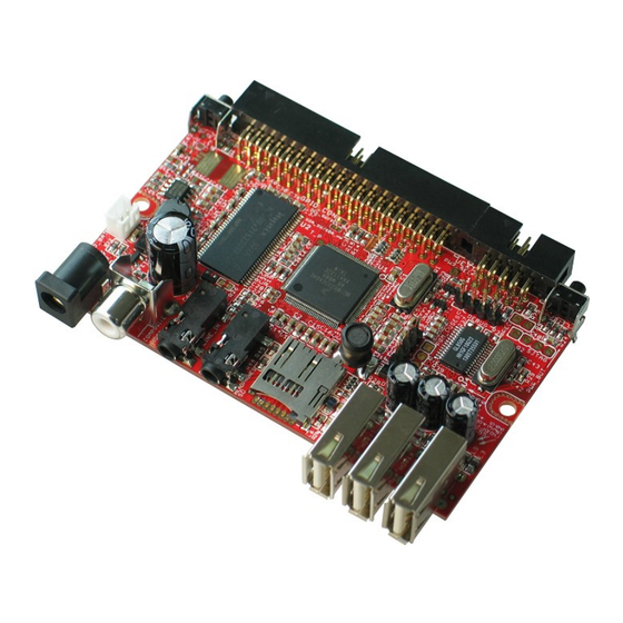
OLIMEX© 2012 OLinuXino User's Manual CHAPTER 3 OLINUXINO BOARD DESCRIPTION 3. Introduction to the chapter Here you get acquainted with the main parts of the board. Note the names used on the board differ from the names used to describe them. For the actual names check the OLinuXino board itself. -
Page 16: Chapter 4 The Imx233 Microcontroller
OLIMEX© 2012 OLinuXino User's Manual CHAPTER 4 THE iMX233 MICROCONTROLLER 4. Introduction to the chapter In this chapter is located the information about the heart of OLinuXino – its microcontroller. The information is a modified version of the datasheet provided by its manufacturers. - Page 17 OLIMEX© 2012 OLinuXino User's Manual — Two stereo line inputs — Microphone input — SPDIF digital out 16-Channel Low-Resolution ADC — 6 independent channels and 10 dedicated channels — Resistive touchscreen controller — Temperature sensor controller — Absolute accuracy of 1.3% —...
- Page 18 OLIMEX© 2012 OLinuXino User's Manual — Provides full path from color-space conversion, scaling, alpha-blending to rotation without intermediate memory access — Bi-linear scaling algorithm with cropping and letterboxing — Alpha-blend, BITBLT, color-keying — Memory efficient block-based rotation engine — Supports up to eight overlays ...
- Page 19 OLIMEX© 2012 OLinuXino User's Manual — I S, left-justified, right-justified, and non-standard formats Customer-Programmable One-Time-Programmable (OTP) ROM via Integrated eFuse Block — Resistor-less boot mode selection — 128-bit boot mode crypto key — Boot mode specification of NAND characteristics for device that the customer is soldering to the board.
-
Page 20: Chapter 5 Control Circuity And Hardware Modules
OLIMEX© 2012 OLinuXino User's Manual CHAPTER 5 CONTROL CIRCUITY AND HARDWARE MODULES 5. Introduction to the chapter Here you can find information about reset circuit and quartz crystals locations, the power supply circuit is discussed. 5.1 Reset OLinuXino's reset circuit includes R42 (47KΩ), R10 (47 Ω), T1, T2, Q1 and a RESET button. The RESET is specific for the fact that it is accomplished when the quartz is disconnected using 3.3V... -
Page 21: Power Supply Circuit
OLinuXino User's Manual 5.3 Power supply circuit The power supply circuit of OLinuXino-MINI allows flexible input supply from 6V to 16V direct current. This means a wide range of power supplies, adapters, converters are applicable. The maximum amperage the board can draw is 1A. - Page 22 OLIMEX© 2012 OLinuXino User's Manual Note that the whole 3.3V part is not mounted (elements marked as NA) by default because we use the internal 3.3V DC-DC convertor in the iMX233. However, the internal DC-DC in the processor is not very reliable when a lot of current is required. It is better to mount the elements of the 3.3V part circuit if you wish to use 3.3V at heavier loads.
-
Page 23: Chapter 6 Connectors And Pinout
OLIMEX© 2012 OLinuXino User's Manual CHAPTER 6 CONNECTORS AND PINOUT 6. Introduction to the chapter In this chapter are presented the connectors that can be found on the board all together with their pinout and notes about them. Jumpers functions are described. Notes and info on specific peripherals are presented. -
Page 24: Uart Debug
OLIMEX© 2012 OLinuXino User's Manual 6.1.1 UART debug The first one is a debug UART interface – U_DEBUG. You can use our USB-SERIAL-CABLE for debugging via the UART. Note on how to use the U_DEBUG with USB-SERIAL-CABLE-F which has RED GREEN BLUE wires GND=BLUE, RX(INPUT)=GREEN, TX(OUTPUT)=RED. -
Page 25: Classic Jtag Debug
OLIMEX© 2012 OLinuXino User's Manual other options in the digital control block which might interest you and our advice is to check the iMX233's datasheet released by Freescale. SJTAG Pin # Signal Name Processor Pin # 1 3.3VREG 2 GND... - Page 26 6 SSP1_CMD 7 SSP1_DATA3 8 SSP1_DATA2 Notice that the pad numeration is written at the bottom of OLinuXino-MINI under the microSD card connector. Please check the manual part for microSD card for a schematic of the pins. Page 26 of 48 Downloaded from Elcodis.com...
-
Page 27: Sd/Mmc Slot
OLIMEX© 2012 OLinuXino User's Manual 6.2 SD/MMC slot The microSD card slot is a standard 8pin connector. We have tested a number of microSD cards on the OLinuXino boards and all of them worked fine regardless manufacturer or capacity. However, keep in mind that some of the lower quality microSD cards might draw too much current from the slot which might cause power-state problems. -
Page 28: Uext Module
OLIMEX© 2012 OLinuXino User's Manual Notice that the pad numeration is written at the bottom of OLinuXino-MINI under the microSD card connector. When removing the card, please make sure that you release it from the connector by pushing and NOT by pulling the card directly (this can damage both the connector and the microSD card). -
Page 29: Gpio (General Purpose Input/Output) 40Pin Connector
OLIMEX© 2012 OLinuXino User's Manual UEXT connector Pin # Signal Name Processor Pin # 1 +3.3VREG 2 GND 30, 35, 98, 105, 112, 118 3 AUART1_TXD 4 AUART1_RXD 5 I2C_SCL 34(default) OR 11* 6 I2C_SDA 31(default) OR 15* 7 PIN9/LCD_D08/SSP2_MISO... - Page 30 The hardware is associated differently in the Linux following the GPIO naming conventions suggested in the iMX233 datasheet. You can check the connection between Linux naming of the pin, Olimex naming of the pin and the consecutive connector pin number in the table below. The Page 30 of 48 Downloaded from Elcodis.com...
- Page 31 OLIMEX© 2012 OLinuXino User's Manual ones filled with “Not implemented” doesn't have Linux support by the time of writing and will be updated overtime. “Linux GPIO” is the one you should use in Linux (the one in the datasheet); “OLinuXino name” is the pin as written on the bottom of the board. ”OLinuXino GPIO Connector #”...
-
Page 32: Usb Hosts
Below you can find the GPIO_CON as seen in the schematic: When looking at the bottom of OLinuXino-MINI near the GPIO connector there is also an additional GND pad named GND_PIN which is a fast way to have access to a ground signal. -
Page 33: Pwr Jack
USB_PWR_A USB_HOST_D- USB_HOST_D+ 6.6 PWR Jack The power jack used is the typical 2.5mm one used by Olimex in most of our products. You should provide between 6 and 16 volts @ 1A to the board. Pin # Signal Name Power Input More info about the power supply can be found in chapter 5 of this manual. -
Page 34: Headphones And Line-In Connector
OLIMEX© 2012 OLinuXino User's Manual 6.7 Headphones and line-in connector Standard audio jack and phone jack are mounted for the audio interfacing. Headphones/Audio out connector Pin# SIGNAL NAME Processor Pin# L channel R channel GND pins The headphones resistance is 16 Ohms! -
Page 35: Battery Connector
OLIMEX© 2012 OLinuXino User's Manual 6.8 Battery connector When using the battery connector keep in mind that it is an energy solution that wouldn't be able to power the board and all the peripherals. The voltage of a 3.7V LIPO battery would be enough to power the processor and the memory but probably won't be enough to power all the devices you mount on the USB hosts. - Page 36 OLIMEX© 2012 OLinuXino User's Manual location: D03, D02, D01 and D00. They are located on the top of the board between the processor and 40pin GPIO connector. Note that the jumpers are SMD type and opening a jumper would require cutting, closing a jumper would require soldering. To be able to do the quoted operations you will need basic engineering skills and experience.
-
Page 37: Jumper Description
2) 3.3V_E open (unsoldered/cut), 3.3VIO_E closed (soldered) In the default variant 1) the board uses the mounted by OLIMEX DC-DC 3.3V convertor which when the board is powered by external supply is the better alternative. However, if you use battery it will not power the chip handling the USB and the LAN functionality. -
Page 38: Boot Mode Selecting Jumpers
Xylinx HY5DU121622D LED1 + Power LED 6.14 Accessories Here you will find additional information for Olimex products you can use with OLinuXino-MINI purchase 6.14.1 USB-SERIAL-CABLE-F The cable for the U_DEBUG interface that can be purchased for additional cost has three cables. It... - Page 39 OLIMEX© 2012 OLinuXino User's Manual is important to specify in your purchase order whether you want the USB-SERIAL-CABLE-F variant with male of female connectors. Page 39 of 48 Downloaded from Elcodis.com electronic components distributor...
-
Page 40: Chapter 7 Block Diagram And Memory
OLIMEX© 2012 OLinuXino User's Manual CHAPTER 7 BLOCK DIAGRAM AND MEMORY 7. Introduction to the chapter On the next page you can find a memory map for this family of processors. It is strongly recommended to refer to the original datasheet released by Freescale for one of higher quality. -
Page 41: Processor Block Diagram
OLIMEX© 2012 OLinuXino User's Manual 7.2 Processor block diagram Page 41 of 48 Downloaded from Elcodis.com electronic components distributor... -
Page 42: Physical Memory Map
OLIMEX© 2012 OLinuXino User's Manual 7.3 Physical memory map Page 42 of 48 Downloaded from Elcodis.com electronic components distributor... -
Page 43: Chapter 8 Schematics
8.1 Eagle schematic OLinuXino schematic is visible for reference here. You can also find them on the web page for OLinuXino at our site: http://www.olimex.com/dev/imx233-OLinuXino-MINI.html. They are located in HARDWARE section. The EAGLE schematic is situated on the next page for quicker reference. - Page 44 OLIMEX© 2012 OLinuXino User's Manual DCDC_VDDD VDDD1 EMI_A00 VDDD3 EMI_A01 512Mb DDR SDRAM (32Mx16) EMI_A02 EMI_A03 22uF/6.3V 22uF/6.3V VSSD2 EMI_A04 VSSD1 2.5V EMI_A05 HY5DU121622D(L)T(P)-J 3.3VIO 22uF/6.3V EMI_A06 VDDIO33_1 EMI_A07 22uF/6.3V PIN6/LCD_D05 VDDIO33_3 EMI_A08 EMI_A09 22uF/6.3V VDDIO_EMIQ EMI_A10 100nF VDDIO_EMI1 100nF EMI_A11 2.5V...
-
Page 45: Physical Dimensions
OLIMEX© 2012 OLinuXino User's Manual 8.2 Physical dimensions Note that all dimensions are in inches. The three highest elements on the board in order from the tallest to the shortest are: capacitor C68 – 16.2mm (0.640'') over the pcb; USB host connectors – 13.6mm (0.525''); composite connector –... -
Page 46: Chapter 9 Revision History And Support
OLIMEX© 2012 OLinuXino User's Manual CHAPTER 9 REVISION HISTORY AND SUPPORT 9. Introduction to the chapter In this chapter you will find the current and the previous version of the document you are reading. Also the web-page for your device is listed. Be sure to check it after a purchase for the latest available updates and examples. -
Page 47: Board Revision
The web page you can visit for more info on your device is http://www.olimex.com/dev/imx233- OLinuXino-MINI.html. You can get the latest updates on the software at: https://github.com/OLIMEX/OLINUXINO. The OLinuXino Linux images sources: https://github.com/Freescale/fsl-community-bsp-platform. ORDER CODES: iMX233-OLinuXino-MAXI – the best version of OLinuXino featuring Ethernet controller iMX233-OLinuXino-MINI –... -
Page 48: Product Support
OLinuXino User's Manual 9.3 Product support For product support, hardware information and error reports mail to: support@olimex.com. Note that we are primarily a hardware company and our software support is limited. Please consider reading the paragraph below about the warranty of Olimex products.
Need help?
Do you have a question about the OLinuXino-MINI and is the answer not in the manual?
Questions and answers