MarinAire
R R
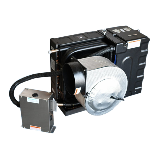
Marine Air Conditioner
User's and Installation Manual
Applies to all MSBA models
Please read this manual before use
Keep this manual safe for future reference
Installation and after sales services should be performed
by marine AC mechanics


Need help?
Do you have a question about the MSBA Series and is the answer not in the manual?
Questions and answers