
Related Manuals for Schaltbau C137 Series


Summary of Contents for Schaltbau C137 Series
- Page 1 Contactors C137, C163, C164, C165 series Single pole contactors for battery voltages Installation and maintenance instructions Manual B60-M.en...
-
Page 2: Table Of Contents
Document Revision History Date Rev. Level Description Pages 2019-05-24 First release Content Important basic information ..................4 Legal notes ..........................4 Conventions for this manual ..................... 4 General and security information ................4 Observing the instructions ....................4 User obligations ........................5 Intended use ........................... - Page 3 Installation ........................18 Mechanical installation .....................18 Dimensions and further technical specifications ............18 Preliminaries .........................18 Correct mounting positions ....................18 Required minimum clearance ..................19 Ventilation requirements ....................19 Safety ............................19 Required tools and auxiliaries ..................19 Install the contactor ......................19 DIN rail mounting........................20 Electrical installation ......................21 Electrical data and further technical specifications ..........21 Preliminaries .........................21 Safety ............................22...
-
Page 4: Important Basic Information
1. Important basic information 1.1 Legal notes CAUTION Without prior written consent of Schaltbau GmbH, this Indicates a hazardous situation with a low level of manual is not allowed to be electronically or mechani- risk which, if not avoided, may result in minor or cally reproduced –... -
Page 5: User Obligations
The contactors have been designed and tested ac- The catalogue B60 is available under: cording to national and international standards. https://www.schaltbau.com/en/media-library/ Due to their unique features they can also be used in a variety of applications. The contactors must only be used under operating conditions according to the technical specification and the instructions in this manual. -
Page 6: Dangers And Security Measures
Dangers and security measures 3. Dangers and security measures 3.1 Electrical dangers DANGER The contactors are used to switch voltage. The touching of electrically conducting parts may result in serious injuries or even death! Energized parts are all metal parts belonging directly to one of the circuits or wires leading there. All other visible metal parts and wires may also be energized in the case of a failure. -
Page 7: Measures For Avoiding Damages And Malfunctions
Dangers and security measures 3.3 Measures for avoiding damages and malfunctions NOTICE Aggressive fluids may damage the contactors. Make sure that the contactors are not exposed to aggressive fluids. NOTICE Improper handling of the contactors, e.g. when hitting the floor with some impact, can result in breakage, cracks and deformation. -
Page 8: Product Information
With its proven line of C137 through C165 Series con- Starting lift/lower control as well as speed and di- tactors Schaltbau offers a scalable solution for handling rectional controls of industrial trucks direct current loads in the range of 40 A to 220 A for the Heater and air conditioning control of electric lo- most common battery voltages up to 110 V. -
Page 9: Survey Of The C137, C163, C164, C165 Series (Stock Items)
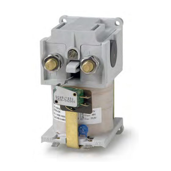
Product information 4.5 Survey of the C137, C163, C164, C165 series (stock items) SPST-NO contactor C137 C Fig. 1: SPST-NO Contactor C137 C, standard version Fig. 2: SPST-NO Contactor C137 C, fitted with auxiliary contact (F) and varistor (G) or diodes (H) Mounting holes for screws M3, Tightening torque 2 Nm Mounting holes for screws M3, Tightening torque: 2 Nm Plasma exits... -
Page 10: Changeover (Spdt) Contactor C137 H
Product information Changeover (SPDT) contactor C137 H Fig. 3: Changeover (SPDT) contactor C137 H, Fig. 4: Changeover (SPDT) contactor C137 H, fitted with standard version auxiliary contact (F) an varistor (G) or diodes (H) Mounting holes for screws M3, Tightening torque: 2 Nm Mounting holes for screws M3, Tightening torque: 2 Nm Plasma exits Plasma exits... -
Page 11: Spst-No Contactor C163 C
Product information SPST-NO contactor C163 C Fig. 5: SPST-NO contactor C163 C, standard version Fig. 6: SPST-NO Contactor C163 C, fitted with auxiliary contact (F) and varistor (G) or diodes (H) Mounting holes for screws M5, Tightening torque: 6 Nm Mounting holes for screws M5, Tightening torque: 6 Nm Plasma exits Plasma exits... -
Page 12: Changeover (Spdt) Contactor C163 H
Product information Changeover (SPDT) contactor C163 H Fig. 7: Changeover (SPDT) contactor C163 H, Fig. 8: Changeover (SPDT) contactor C163 H, fitted with standard version auxiliary contact (F) and varistor (G) or diodes (H) Mounting holes for screws M5, Tightening torque: 6 Nm Mounting holes for screws M5, Tightening torque: 6 Nm Plasma exits Plasma exits... -
Page 13: Spst-No Contactor C164 C
Product information SPST-NO contactor C164 C Fig. 9: SPST-NO contactor C164 C, standard version Fig. 10: SPST-NO Contactor C164 C, fitted with auxiliary contact (F) and varistor (G) or diodes (H) Mounting holes for screws M5, Tightening torque: 6 Nm Mounting holes for screws M5, Tightening torque: 6 Nm Plasma exits Plasma exits... -
Page 14: Changeover (Spdt) Contactor C164 H
Product information Changeover (SPDT) contactor C164 H Fig. 11: Changeover (SPDT) contactor C164 H, Fig. 12: Changeover (SPDT) contactor C164 H, fitted with standard version auxiliary contact (F) and varistor (G) or diodes (H) Mounting holes for screws M5, Tightening torque: 6 Nm Mounting holes for screws M5, Tightening torque: 6 Nm Plasma exits Plasma exits... -
Page 15: Spst-No Contactor C165 C
Product information SPST-NO contactor C165 C Fig. 13: SPST-NO contactor C165 C, standard version Fig. 14: SPST-NO Contactor C165 C, fitted with auxiliary contact (F) and varistor (G) or diodes (H) Mounting holes for screws M5, Tightening torque: 6 Nm Mounting holes for screws M5, Tightening torque: 6 Nm Plasma exits Plasma exits... -
Page 16: Changeover (Spdt) Contactor C165 H
Product information Changeover (SPDT) contactor C165 H Fig. 15: Changeover (SPDT) contactor C165 H, Fig. 16: Changeover (SPDT) contactor C165 H, fitted with standard version auxiliary contact (F) and varistor (G) or diodes (H) Mounting holes for screws M5, Tightening torque: 6 Nm Mounting holes for screws M5, Tightening torque: 6 Nm Plasma exits Plasma exits... -
Page 17: Storage
► Return shipments Schaltbau recommends to keep the original packing box for any return shipments. If no original packing box is available care must be taken to pack the contactor in a way that prevents damage during shipment. -
Page 18: Installation
In order to secure the mounting screws against given in the respective data sheets or in our catalogue. self-loosening, appropriate screw locking ele- Refer to our catalogue B60. ments have to be provided. Schaltbau strongly The catalogue is available under: recommends Schnorr-Washers (or similar) to se- https://www.schaltbau.com/en/media-library/ cure the screws. -
Page 19: Required Minimum Clearance
Installation Required minimum clearance Required tools and auxiliaries - Socket wrench set NOTICE - Hexagon socket wrench set Switching electrical currents at high voltages will - Torque wrench produce arcing and plasma may exit out of the arc Install the contactor chambers. -
Page 20: Din Rail Mounting
DIN rail mounting The contactor can also be installed by means of DIN rail mounting. DIN rail mounting sets can be ordered from Schaltbau GmbH. The installation is possible either at the rear side or at the bottom side of the contactor. -
Page 21: Electrical Installation
10 Nm In order to secure the terminal nuts against self- loosening, appropriate screw locking elements have to be provided. Schaltbau recommends Schnorr-Washers (or similar) to secure the nuts. The terminal nuts against must be tightened with the determined torque (refer to the table above). -
Page 22: Safety
Installation Safety DANGER The contactors are used to switch voltage. The touching of electrically conducting parts may result in serious injuries or even death! Energized parts are all metal parts belonging directly to one of the circuits or wires leading there. All other visible metal parts and wires may also be energized in the case of a failure. -
Page 23: Connect The Coil Terminals
Plug the prepared control wires with the flat re- ceptacles (3) to both coil terminals A1 and A2 (4). A 2.8 x 0.5 mm Fig. 22: C137 Series: Connect the auxiliary contact (SPDT) A 6.3 x 0.8 mm Fig. 24: C137 Series: Connect the coil terminals A 6.3 x 0.8 mm... -
Page 24: Connect The Main Contacts
Make sure, that both contact bolts (1) are equipped Put the washers (4) on the contact bolts (1). with washers and counter nuts (6). - Schaltbau recommends Schnorr-Washers (or Put the cable lugs (2) on the contact bolts (1). similar) to secure the nuts. -
Page 25: Connect The Normally Closed Contacts (Changeover (Spdt) Contactors Only)
Put the washers (4) on the contact bolts (1). Make sure, that both contact bolts (1) are equipped with washers and counter nuts (6). - Schaltbau recommends Schnorr-Washers (or similar) to secure the nuts. Contactors C137/C163/C164/C165 – Installation and Maintenance Instructions... -
Page 26: Tie Bars For Contactors In Series Connection
(9) on the contact bolts (1). connection Put the washers (4) on the contact bolts (1). To realise series connections with contactors, Schaltbau - Schaltbau recommends Schnorr-Washers (or offers suitable connecting tie bars. For dimensions and similar) to secure the nuts. -
Page 27: Checks
Check the pull-in voltage and drop-off voltage according to the requirements of Schaltbau. Refer to catalogue B60. Check the laying of cables. Cables must not be squeezed or bent. If applicable bundle the cables and secure them with cable ties. -
Page 28: Maintenance
Maintenance 8. Maintenance Note the expert knowledge which is essential for car- rying out maintenance work, mentioned in chapter “2. General and security information”. 8.1 Safety DANGER The contactors are used to switch voltage. The touching of electrically conducting parts may result in serious injuries or even death! Energized parts are all metal parts belonging directly to one of the circuits or wires leading there. -
Page 29: Regular Check Activities
Maintenance NOTICE Detent-edged rings and detent-edged washers have a limited life time. After 3 times opening of screws secured with detent-edged rings or detent-edged washers, the rings or washers must be replaced by new ones. Record the frequency of screw opening in the work log. -
Page 30: Check The Main Contacts
Maintenance Component Visual inspection Measures Auxiliary contact Check for: In case of faults: damage or wear and tear replace auxiliary contact, refer to section “8.3 Corrective maintenance”/ The auxiliary contact is visible for a simple optical “Replace the auxiliary contact”. inspection from the outside. - Page 31 Maintenance Contactor types C164 and C165 Unscrew the 3 screws (3) and remove them. Lift the arc chamber (2) upwards and remove it. - The main contacts are now accessible and can be checked. See “Check the main contacts for wear and tear”...
- Page 32 Maintenance Check the main contacts for wear and tear If the main contacts and the normally closed con- tacts are not damaged and not heavily worn, then SPST-NO contactor types C 137 C, C163 C, C164 C re-install the arc chamber cover. and C165 C Check the main contacts for damage, wear and tear, as well as traces of burn-off (slightly sooting...
-
Page 33: Corrective Maintenance
Maintenance 8.3 Corrective maintenance The contactors are maintenance-free. Therfore there is no general provision for replacing components during its service life. Replace the auxiliary contact Under normal working conditions (if there were no short circuits in the control circuit) the life time of the auxiliary contact exceeds those of the contactors. -
Page 34: Spare Parts
Spare parts 9. Spare parts Important! When ordering spare parts, always inform Schaltbau about the exact type and the article number of the contactor. You can find these data on the rating plate. Designation Article-No. Type of contactor Auxiliary contact... - Page 35 Notes Notes Contactors C137/C163/C164/C165 – Installation and Maintenance Instructions 2019-05-24 / V1.0...
- Page 36 High-voltage heaters ■ High-voltage roof equipment ■ Equipment for electric brakes ■ Design and engineering of train electrics to customer requirements We reserve the right to make technical alterations without prior notice. Printed in Germany For updated product information visit www.schaltbau-gmbh.com..
Need help?
Do you have a question about the C137 Series and is the answer not in the manual?
Questions and answers