Table of Contents
Advertisement
Quick Links
Specifications
Dimensions
5.0" (12.7 cm)
14.75"
(37.5 cm)
(35.8 cm)
All ½"
Contact Information
Mailing
Address:
Date and Revision
Web Site:
April 2020, Revision A
900-00268-01-001 REV A
©2020 OutBack Power. All Rights Reserved.
12.0"
14.1"
(30.5 cm)
7.3" (18.5 cm)
Specifications
Voltage
DC Input
Power Draw
Enclosure Rating
3.75" (9.5 cm)
Ambient Temperature
LED Indicators
Knockouts
6.6" (17.8 cm)
th
17825 – 59
Avenue NE
Suite B
Arlington, WA 98223 USA
www.outbackpower.com
IMPORTANT:
Not intended for use with
life support equipment.
Quick Start Guide
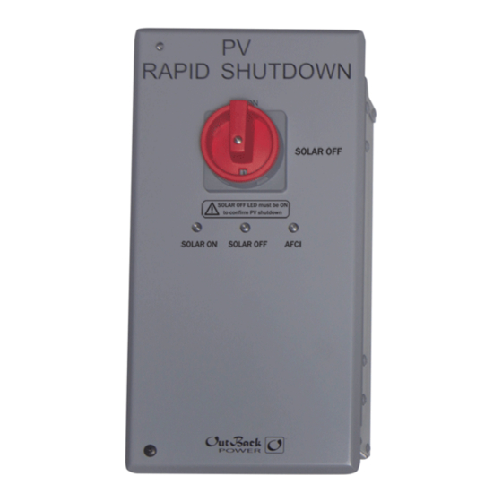
Rapid Shutdown Initiator
Audience
These instructions are for use by qualified personnel who meet all local and governmental code requirements
for licensing and training for the installation of electrical power systems with AC and DC voltage up to 600 volts.
Failure to install or use this equipment as instructed in the literature can result in damage to the equipment that
may not be covered under the limited warranty. This product is only serviceable by qualified personnel.
Product
The Rapid Shutdown Initiator (RSI) initiates the rapid shutdown function
required for a PV array with module-level power electronics (MLPE) and other
devices, as part of a rapid shutdown system, for compliance with 2017 NEC 690.
Features
1 R
S
switch
APID
HUTDOWN
2 S
O
LED indicator
OLAR
N
3 S
O
LED indicator
OLAR
FF
4 A
LED indicator
FCI
NOTE: The red A
indicator is not functional unless used with the ICS Plus family
FCI
of PV combiners.
24 Vdc ± 3%
5 ½" Electrical knockouts
24 Vdc ± 3%
(EKO) × 3
0.06 Adc
UL Type 3R
Application with FireRaptor MLPE
–25 to 60°C
S
O
OLAR
N
S
OFF
OLAR
This product will activate the rapid-shutdown circuit of the FM100 charge controller if connected to MLPE devices.
A
FCI
It may optionally activate an inverter on/off circuit to de-energize the inverter. This product is intended for
½"
installations requiring more than 40 IMO FireRaptor OBFRS-ESW1 units. Up to 114 FireRaptor units may be
used per RSI. Up to six RSI units may be used on a single system.
When the RSI opens for a rapid shutdown event, it removes power from all FireRaptor devices. The RSI A
C
/S
O
connection will place the FM100 controller into a rapid shutdown state. The controller's
OMMAND
TATUS
UTPUT
rapid shutdown terminals may be connected to other FM100 controllers for a "daisy-chained" rapid shutdown
configuration, or may be connected to the inverter's on/off circuit. See the opposite side of this sheet for instructions.
Other Applications
Similar applications are also possible with other MLPE products such as the TIGO TS4-A-S and TS4-A-F.
Initiates the rapid shutdown function. Turning to the
S
O
position removes the 24-volt signal
OLAR
FF
enabling MLPE devices to operate. This switch can
be secured with a padlock.
Green LED indicator. It illuminates when DC voltage
is present and the R
S
switch is in the
APID
HUTDOWN
S
O
position.
OLAR
N
Red LED indicator. S
O
must be illuminated to
OLAR
FF
confirm PV shutdown. The S
O
indicator tells
OLAR
FF
responders that the R
S
switch is in the
APID
HUTDOWN
S
O
position to create a "safe" condition.
OLAR
FF
Red LED indicator; illuminates when receiving an
"arc fault" signal from an ICS Plus combiner.
These accommodate conduit and a UL 514-compliant
fitting for communication wires.
1
2
3
4
5
5
5
R
UX
SI
Advertisement
Table of Contents

Subscribe to Our Youtube Channel
Related Manuals for EnerSys OutBack Power Rapid Shutdown Initiator


Summary of Contents for EnerSys OutBack Power Rapid Shutdown Initiator
- Page 1 Quick Start Guide Specifications Rapid Shutdown Initiator Dimensions Audience 5.0” (12.7 cm) These instructions are for use by qualified personnel who meet all local and governmental code requirements for licensing and training for the installation of electrical power systems with AC and DC voltage up to 600 volts. Failure to install or use this equipment as instructed in the literature can result in damage to the equipment that may not be covered under the limited warranty.
- Page 2 Application with FireRaptor MLPE RSI Connections The RSI is equipped with terminal connections for power, input J4 is the R . These are dry contacts which can receive external commands. TATUS NPUT signals, and output signals. An external switch or relay can send a “Safe” signal to J4 from another location. ...
Need help?
Do you have a question about the OutBack Power Rapid Shutdown Initiator and is the answer not in the manual?
Questions and answers