
Related Manuals for OTC Tools 3182

Summary of Contents for OTC Tools 3182
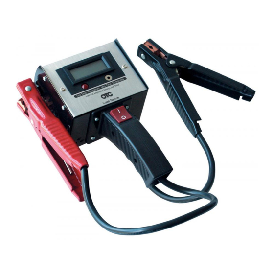
- Page 1 3182 Digital Battery Load Tester r T es te r te ry L o ad /A lt er n at o D ig it al 13 0 A m p B at OPERATING INSTRUCTIONS...
-
Page 2: Safety Precautions
SAFETY PRECAUTIONS When Working on Vehicles • Always wear approved eye protection. • Always operate the vehicle in a well-ventilated area. Do not inhale exhaust gases—they are very poisonous! • Never smoke or have open flames near vehicle. Vapors from gasoline and charging batteries are highly flammable and explosive. Always keep a fire extinguisher suitable for gasoline/electrical/chemical fires handy. • Always keep yourself, tools, and test equipment away from all moving or hot engine parts. • Never lay tools on vehicle battery. You may short the terminals together, causing harm to yourself, the tools, or the battery. • Always turn ignition key OFF when connecting or disconnecting electrical components, unless otherwise instructed. -
Page 3: Test Preparation
Battery Load Tester The 3182 Digital Battery Load Tester is a hand-held, diagnostic tool used to test 12V (volt) and 6V lead-acid type automotive batteries. A 10-second test determines the condition of the battery: Good, Weak or Bad. Further testing will identify possible problems in the charging and starting systems. Tests can be performed on fully or partially charged batteries by inspecting the electrolyte or open-circuit voltage and adjusting the values for temperatures other than 70°F (21.1°C). • If the electrolyte is accessible, measure its specific gravity with a hydrometer. The specific gravity reading should be 1.225 or higher at 70°F (21.1°C). For every 10°F (5.6°C) above/below 70°F (21.1°C), add/subtract 0.004 to/from the reading. • The open-circuit voltage should be at least 12.45V at 70°F (21.1°C). The Battery Load Tester contains a four-character LCD (liquid crystal display) to display battery voltage, a switch to apply the test load and a red LED that is used to indicate the condition of the alternator. The tester is powered by the battery under test. CAUTION! • Test procedures and information provided in this manual are intended as general guidelines for engine tune-up and adjustments only. Consult the applicable vehicle service manuals for all specific tests. -
Page 4: Vehicle Battery
Vehicle Battery 1. Turn ignition key OFF; not in the ACCESSORIES position (Figure 2). Engine needs to be OFF and all electrical loads must be removed from the battery for proper testing. If loads still exist, refer to the vehicles operator and service manual. 2. If battery is being charged, then stop, turn charger OFF and disconnect clamps or leads. The battery Figure 2 Engine OFF cannot be tested while being charged. 3. The connections must be clean and must make good contact to achieve correct test results. 4. On side-post type batteries, install terminal stud adapters. These are not included, but are available at most automotive parts stores. Battery Temperature The most accurate test results will be obtained when battery temperature is at approximately 70°F (21.1°C). If testing battery between 70°F (21.1°C) and 40°F (4.4°C), add 0.1 volt for every 10°F (5.6°C) below 70°F. If testing a battery between 70°F (21.1°C) and 100°F (37.8°C), subtract 0.1V for every 10°F (5.6°C) -
Page 5: Test Results
3. Press and hold the LOAD SWITCH for 10 seconds. Refer to Figure 4. 4. Observe the voltage on the LCD and note the value. Release the LOAD SWITCH immediately after reading the display. 5. Disconnect the Red clamp from the battery and then the Black clamp. or Te st er tte ry Lo ad /A lte rn at Di gi ta l 13 0 Am p Ba 6. Figure 5 shows the range for a 500 CCA (Cold-Cranking Amperage) battery tested at 70°F (21.1°C). For batteries... -
Page 6: Starting Test
• Battery clamps are securely fastened to the terminals. • Terminals are clean and free of debris for a good electrical continuity. • If a side-post type battery is being tested, verify the terminal stud adapters are screwed in tightly. If no fault is detected, then charge battery and retest before replacing the battery. If tester still indicates a bad battery, then replacement is required. NOTE: A WEAK or BAD indication may be due to excessive resistance caused by a bad connection or corrosion between battery cables and the battery posts. Remove battery cables from battery, connect the tester directly to the posts and retest. -
Page 7: Charging Test
3. Have an assistant turn the ignition switch to the Start Position and crank engine for 15 seconds. If working alone, use a remote starter switch. Do not press the Load Switch. Observe the battery voltage indicated on the display. 4. A healthy starting system, with a good, fully charged battery, should read above 9.0V during this test. 5. Readings below 9.0V may indicate a problem in the starting system. Recharge battery and repeat this test. If voltage readings still remain below 9.0V, then probably either the battery is bad (perform the Load Test), the starter is defective or the cables are loose or corroded. Charging Test This test measures the battery voltage while the engine is running to determine if the charging system is operating properly. 1. Start the vehicle and allow it to warm-up. This may take 10 to 15 minutes. 2. Turn engine OFF. 3. When performing the Charging Test, the battery should be partially discharged. Turn the ignition switch to the ACCESSORIES position and turn headlights ON and fan to HIGH for 1 minute. 4. When done, turn headlights and fan OFF and then turn ignition switch to the OFF position. 5. While observing polarity, connect the tester across the battery posts: Red to positive (+), Black to negative (-). Refer to Figure 6. 6. Start engine and run at fast-idle (1200-1500 RPM). A healthy 12V charging system should maintain readings between 13.5V and 15.5V. -
Page 8: Alternator Test
Alternator Test This test identifies problems associated with the alternator. 1. As shown in Figure 7, connect the tester’s clamps to the vehicle’s battery posts: Red to positive (+), Black to negative (-). Connect the test lead to the tester and positive terminal on alternator. On GM alternators, attach the test lead to terminal Nº 1 without disconnecting the plug. 2. Start engine and allow it to idle. 3. If a GM alternator is being tested, observe the tester’s Red LED and do not press the LOAD SWITCH. Otherwise, continue with Step 4. • If the LED flashes On and goes OFF, or never comes ON, then the Diode Trio is functioning properly. • If the LED stays ON, then the Diode Trio might be defective. The alternator needs repair or replacement. 4. Rev the engine to a fast idle (1200-1500 RPM). CAUTION! • The Battery Load Tester becomes hot when applying the load. Allow tester to cool between discharges; about 2 minutes. In warm temperatures, allow more time to cool.
Need help?
Do you have a question about the 3182 and is the answer not in the manual?
Questions and answers