Table of Contents
Advertisement
Quick Links
Advertisement
Table of Contents

Subscribe to Our Youtube Channel
Related Manuals for MFJ MFJ-4418


Summary of Contents for MFJ MFJ-4418
-
Page 2: Table Of Contents
Internal Settings and Fuses ........................9 JP2: The jumper is accessible by removing the bottom cover. Set the jumper for ......9 F1 Fuse:..............................9 Operation: ..............................9 Programming the MFJ-4418 ........................10 THEORY OF OPERATION........................13 Input Filtering: ........................... 13 SMPS controller:..........................14 MOSFET drivers and transformer: .................... -
Page 3: Introduction & Features
13.8 volts to 12 volts after a short period of time. With this in mind the MFJ-4418 Super Battery Booster corrects all of these problems. With its high efficiency boost regulator circuitry, it will maintain the desired 13.8 volts at up to 25 amps ICAS from voltages as low as 9 volts. -
Page 4: Typical Specifications
MFJ-4418 and ensure the polarity is correct. 3. Plug the output of the MFJ-4418 into your radio and then attach the input to your battery. 4. You are now ready to operate. If not using external switching, depress the enable switch. -
Page 5: System Controls And Indicators
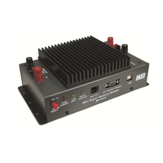
SYSTEM CONTROLS AND INDICATORS Top Inputs and Outputs: Figure 1 Top View 1. 5-Way High Power Binding Post Negative Input. 2. Anderson PowerPole Input. 3. 5-Way High Power Binding Post Positive Input. 4. 5-Way High Power Binding Post Positive Output. 5. -
Page 6: Controls And Indicators
DC Power Connection: The MFJ-4418 is designed to boost voltages as low as 9.5V up to 13.8V at up to 30A peak. At high currents the voltage drop from even large gauge wires can be appreciable for even short runs. -
Page 7: Remote And External Control Connections
This will help reduce the current drain on the battery when the vehicle is off. Not all radios are set up to be able to key the MFJ-4418. In those cases the boost button will have to be set to ON or programmed for “Enable on input at low limit”. There is no RF sense built into the MFJ-4418. -
Page 8: Remote Control
Remote Control: The optional Remote Control MFJ-4416BRC can be used to monitor and control the MFJ-4418 allowing the MFJ-4418 to be mounted in an out of the way place in the vehicle. The connection is a normal CAT-5 cable that plugs into the MFJ-4416BRC and the MFJ-4418 REMOTE CONTROL RJ-45 Jack. -
Page 9: Internal Settings And Fuses
The MFJ-4418 is not designed to boost the voltage of a 6V electrical system up to 13V and will not run on a positive ground system. It will also not reduce the voltage of a 24V or higher system... -
Page 10: Programming The Mfj-4418
MFJ-4418 Battery Booster Manager Program. The installer will place an icon on the desktop to run the program. d. Apply power to the MFJ-4418 and plug in the USB cable between the unit and the computer. The computer should find and use the drivers to communicate with the MFJ-4418. -
Page 11: Figure 9 Battery Booster Manager Window
Write Data Button: This button writes any changes made to the EEPROM on the 4418 making them permanent. If you forget to write the data the MFJ-4418 will automatically save it when the USB connection is closed. It is a good idea to write the data when the changes are made because of the power is interrupted prior to closing the USB port the changes will be lost. - Page 12 This allows you to complete a QSO without the fear of leaving the radio on as the MFJ-4418 will turn off the output voltage at the end of this time unless the ignition is again turned on.
-
Page 13: Theory Of Operation
s. Peak Current Display: This value is the peak current seen during the supply operation. This value is volatile and will be zeroed when the power supply input voltage is removed or the “Reset” button in pressed. t. Average Current Display: This value is the average current delivery by the supply. -
Page 14: Smps Controller
15Volts. The MFJ-4418 provides soft start and this is activated on power up or when the ignition lead senses +12V. The software waits 500 milliseconds for the supply to stabilize and then switches... -
Page 15: In Case Of Difficulty
This is also the high output voltage check and if 15 Volts is exceeded the CPU will shut down the power and boost function protecting the attached radio and the MFJ-4418 from internal or external voltage faults. If this fault occurs the supply is locked out till the power is removed. -
Page 16: Minimum Battery Voltage
Although every effort was made to reduce switching noise RF noise is a possibility. To reduce noise to a minimum ground the case of the MFJ-4418 to the automotive chassis with as short of a wire or grounding braid as possible. Clamp on ferrite beads can be used on the input and out power leads to further reduce noise. -
Page 17: Schematics
Schematics Figure 11 SMPS Section Schematic... -
Page 18: Figure 12 Control Section Schematic
Figure 12 Control Section Schematic... -
Page 19: Figure 13 Cpu Section
Figure 13 CPU Section... -
Page 20: Full 12-Month Warranty
MFJ Enterprises, Inc. at the time of warranty service. MFJ Enterprises, Inc. shall have the discretion to deny warranty without dated proof-of- purchase.
Need help?
Do you have a question about the MFJ-4418 and is the answer not in the manual?
Questions and answers