Advertisement
Quick Links
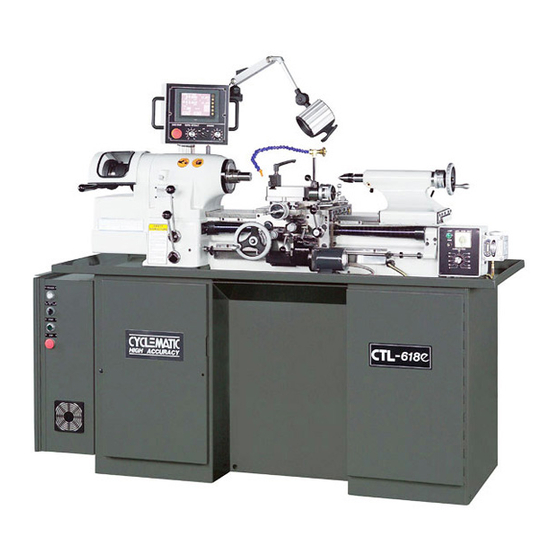
Special features
Operation manual
This lathe doesn't use threading gearbox, instead
computer-controlled servo motor is directly linked
to the leadscrew. Just use your finger to select
desired thread pitch on the touchscreen display,the
threads come out absolutely precise and you
totally eliminate problems with specialized
threads.The disply also shows spindle speed,
cutting feed rate and DRO functions.
Good for pitch and module turning processing without any gears in gearbox. Easy exchange of inch and
metric system, accuracy goes up to three degits after decirnal point.
.HOME > PRODUCT > CTL-618e
Specification
Optional
Advertisement

Summary of Contents for CYCLEMATIC CTL-618e
- Page 1 .HOME > PRODUCT > CTL-618e Special features Specification Operation manual Optional This lathe doesn't use threading gearbox, instead computer-controlled servo motor is directly linked to the leadscrew. Just use your finger to select desired thread pitch on the touchscreen display,the...
- Page 2 Since CTL-618e already has custom IC and a LCD panel to enable threading control, the next logical step is to integrate DRO functions into it for an all-in-one versatile machine. And CTL-618e has in-fact done that.
- Page 3 Radius Turning Taper Turning Rear Tool Holder Slide Quick Change Tool Attachment Attachment Assembly MODEL CTL-618e With Chuck 150 mm (6") With Expanding Collets 76 mm (3") With Round 5C Collets 27 mm (1-1/16") Spindle Capacity With Hexagon 5C Collets 22 mm (7/8")
- Page 4 W.) TAILSTOCK BODY LOCK OPERATION The model CTL-618e series machine is built for easy and safe operation and excellent manufacturing of work in process. The machine is built with high quality material, and carefully to exacting standards that guarantee the life, economical use, accuracy, and minimum maintenance of the machine.
- Page 5 CTL-618e 1. Put pads C (Figure B) under each of six points. 2. Loose set screw A (Figure B) 3. Insert a pin wrench into the hole B. raise or lower by turning (C.C.W.or .C.W) 4. Tighten set screw A (Figure B) to lock.
- Page 6 When the adjustment is done, tighten set screws. The CTL-618e TOOLROOM LATHE is shipped completely wired and assembled, Turn Cam Switch "A" (Figure 2) to the "OFF" position, then check motor voltage.
- Page 7 Figure 5-Speed Change Unit 2. GEAR BOX AND CLUTCH LUBRICATION Maintain oil level in sight windows "W" (Figure 7). To fill gearbox, remove plug "C"(Figure 7) use Automatic Transmission Fluid Mobil 200 (Esso ATF or equivalent Change oil every 500 hours). To drain oil, remove the Drain Plug "M"...
- Page 8 Figure 10-Control Speed Control Box While you threading, you have to following the steps to set up, first choose the mm/inch set the pitch size by touch screen, and choose the Right hand threador Left hand thread "F" by touch screen, after that choose the pitch "G"...
- Page 9 Figure 12-Feed of Thread Change Figure 13-Carriage Clutches ※CAUTION: PLEASE FOLLOW TOP OF THREAD CHART , THE SPINDLE SPEED DO NOT OVER SPEED . IF SPINDLE SPEED OVER THE LIMIT , THE TOUCH SCREEN WILL APPEAR "SPINDLE OVER" . ALSO THE THERADING FUNCTION WILL NOT WORK .
- Page 10 Figure 16- Speed Control Box Figure 17- Speed Control Box When threading into a blind hole or to a shoulder without a thread relief. The lead screw half nut if engaged at the start of the threading work is completed. Left or right hand threads are controlled by Control lever "D" (Figure 18), the lever is joined with the control bar "B"...
- Page 11 Run spindle at approximately 1000 rpm. Move lever "G" (Figure 21) to center "STOP" position and let the spindle coast to stop. This is done to equalize belt tension. Loosen lock nut "N" (Figure 22) with 19mm wrench. Turn adjusting screw "P" (Figure22) with screwdriver clockwise to tighten belts. Stop machine and check belt tension, there should be approx.1"...
- Page 12 Test collet closer's tension on work piece. If the work piece needs additional gripping pressure, press down on the adjusting finger "F" (Figure 26) and turn Shell Guard "G" (Figure 26) forward and lock. Figure 26-Collet Closer Adjustment Figure 25-Control Speed and Direction Dual dials with Inch and Metric Hand wheel dial "W"...
- Page 13 Cross Slide operation of free and adjustment of clutches are identical with the operation and adjustment of carriage clutches. If CTL-618e TOOLROOM LATHE needs to be used with the taper turning attachment, loosen the screw "S" (Figure 30) with a spanner wrench.
- Page 14 of feed which can best suit to the requested surface finish and production rate, then record the proper settings after testing. Figure 32-AC Motor Figure 33-Power Feed Unit NOTE: WHEN STARTING INTO PRODUCTION. AN OPERATOR CAN SET THE FEED CONTROL "N" TO THE RECORDED REFERENCE SETTING, THEN THE SAME TESTED RESULTS WILL BE OBTAINED.
- Page 15 T-KH-48 T-CT-01 14-1 540-110 No. 20, Lane 50, Ming Shen Rd., Shen Kang Dist., Taichung 429, Taiwan TEL: 886-4-2562-5393, 2562-6509 FAX: 886-4-25620298 E-mail: cymatic@ms23.hinet.net © 2013 CYCLEMATIC MACHINERY CO., LTD. All rights reserved. Design by Taiwan Products, B2BChinaSources, B2BManufactures, Wakema...
Need help?
Do you have a question about the CTL-618e and is the answer not in the manual?
Questions and answers