Table of Contents
Advertisement
0.
GENERAL SAFETY INFORMATION, WARNINGS & CAUTIONS
1.
INSTALLATION
2.
THE USER
3.
SERVICING
4.
DISPOSAL
AQUAMATIC AMV, AMF, HYAV
SERIES COLD WATER PRESSURE BOOSTER SETS
MODELS: AMV-FB, AMV-FE, AMV-ES, AMF, HYAV
Head Office: AGM House, London Rd, Copford, Colchester, Essex CO6 1GT UK
Tel: 01206 215121 Email: aftersales@agm-plc.co.uk
INSTRUCTIONS FOR
ISSUE 27 2/4/2019
Advertisement
Table of Contents

Summary of Contents for Aquatech Pressmain Aquamatic AMV Series
- Page 1 INSTRUCTIONS FOR GENERAL SAFETY INFORMATION, WARNINGS & CAUTIONS INSTALLATION THE USER SERVICING DISPOSAL AQUAMATIC AMV, AMF, HYAV SERIES COLD WATER PRESSURE BOOSTER SETS MODELS: AMV-FB, AMV-FE, AMV-ES, AMF, HYAV ISSUE 27 2/4/2019 Head Office: AGM House, London Rd, Copford, Colchester, Essex CO6 1GT UK Tel: 01206 215121 Email: aftersales@agm-plc.co.uk...
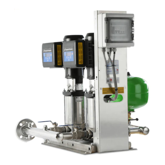
- Page 2 Examples of units manufactured by Aquatech Pressmain are shown below: - Please note: it is also possible for the components to have been sold as separate items, in which case the O&M manual and CE declaration may only be applicable in part.
-
Page 3: Table Of Contents
Aquamatic Series Model number examples: - AquaMatic Cold water pressure booster set series All Variable speed pumps All Fixed speed pumps HY-AV Hydro-pneumatic variable speed, (custom built) pumpset 2to8 Number of pumps Standard vessel (not flow through) Flow Through vessel End Suction pumps Basic controller Enhanced 2020+ controller with BMS... -
Page 4: General Safety Information
Aquamatic Series USER INSTRUCTIONS ................. 16 CUSTOMER ASSURANCE ..................16 COMMISSIONING ....................16 OPERATING INSTRUCTIONS .................. 17 2.3.1 ADDITIONAL WARNINGS ................17 2.3.2 ADDITIONAL CAUTIONS ................17 2.3.3 NORMAL OPERATION - COLD WATER PRESSURE BOOSTER ....... -
Page 5: Warnings
Aquamatic Series Any damage caused to the equipment by misapplication, mishandling or misuse could lead to risk of Electrocution, Burns, Fire, Flooding or injury to people or damage to property dependent upon the circumstances involved. This equipment contains moving/rotating parts that must remain guarded. Removal of or ... -
Page 6: Cautions For Installation
Aquamatic Series 0.1.10 Any damage to equipment, pumpset, vessels, pipework or system components caused by misapplication, mishandling or misuse could lead to Electric shock hazard, Burns hazard, Fire hazard, Flooding hazard or cause injury to people or damage to property. 0.1.11 This equipment may contain moving/rotating parts that must remain guarded. - Page 7 Aquamatic Series Directive (PED). Where units are despatched with “Loose” vessel(s) for assembly on site it is absolutely essential that they be installed as detailed in the instructions using the fittings provided where appropriate. Failure to observe this will nullify compliance with the PED and may present a safety hazard.
-
Page 8: Cautions For Operation/User
Aquamatic Series 0.2.27 EMC - With respect to BS EN61000-3-2 this equipment is defined as ‘professional equipment’ and therefore the installer/user may need to seek permission from the supply utility to connect this equipment to the public low voltage mains supply. 0.2.28 Where “Expansion vessels”... -
Page 9: Cautions For Maintenance
Aquamatic Series exceptions/additions: -In the event of a fire there must be a volt-free signal from the sprinkler system to force the booster set into “fire sprinkler mode” and run all pumps at 100% speed until manually switched off at the mains isolator switch (IS1). This is in accordance with BS9251 code of practice “The sprinkler system is normally only to be turned off following liaison with the fire and rescue service and when deemed safe to do so”. -
Page 10: Installation Instructions
Aquamatic Series INSTALLATION INSTRUCTIONS These instructions are intended for the installer of this pressure booster set. Please follow them carefully. The unit should only be installed by a competent person; A competent person is someone who is technically competent and familiar with safety practices and the hazards involved. Failure to install the equipment as recommended below could invalidate the warranty provided by AquaTech-Pressmain to the purchaser. -
Page 11: Fixing
Aquamatic Series withdraw diaphragms from vessels. remove manifolds from pumps. If necessary, provide overhead lifting eyes for possible future use. Any Hydraulic Accumulator supplied should be located as near as possible to the discharge side of the pumpset. Should any of these location conditions not be satisfied AquaTech-Pressmain reserve the right to charge labour on any warranty work required on the pumpset. - Page 12 Aquamatic Series MAX PERMISSIBLE MOVEMENT BORE NOM. AXIAL AXIAL SHEAR ANGULAR MOVEMENT Length EXTN COMP (mm) (mm) (mm) (mm) (mm) Compression Extension Shear Angulation Fig. 1.3 Flexible pipework connections 1.3.4.7 Where Hydraulic Accumulator(s)/Expansion Vessel(s) are supplied as a loose item, they must be installed/connected correctly before operating the equipment, otherwise serious damage from over-pressure/pump overheating could occur (see also 1.3.5 for correct mounting).
-
Page 13: Flow Through Vessels
Contact AquaTech Pressmain for further information. Set the air cushion pre-charge pressure to the correct level (see section 2.4), dependent on the application required for the vessel. -
Page 14: Electrical
Aquamatic Series 1.3.6 ELECTRICAL WARNING: DO NOT TOUCH ANY LIVE PARTS FOR AT LEAST 5 MINUTES AFTER SWITCHING OFF THE POWER TO ALLOW CAPACITORS TO DISCHARGE READ GENERAL SAFETY INFORMATION 0.0, WARNINGS 0.1 and CAUTIONS 0.2, 0.3 & 0.4 1.3.6.1 All wiring must comply with the latest edition of local wiring Regulations. -
Page 15: Guidance On Selecting The Correct Earth Leakage Protection Device For Booster Sets
Aquamatic Series A B C D E F G H J K L M N O P R S T U V W X Y Z PCB2 BMS volt free outputs max 240VAC 50Hz 1.5A 2020PLUS CONTROLLER PCB1 INTERFACE Display CARD EPB-120134 4-Channel... -
Page 16: User Instructions
Aquamatic Series USER INSTRUCTIONS CUSTOMER ASSURANCE AQUATECH-PRESSMAIN ASSURE YOU THAT IF ANY PART OF THIS EQUIPMENT BECOMES DEFECTIVE DUE TO FAULTY MANUFACTURE OR MATERIALS WITHIN 24 MONTHS FROM THE DATE OF INVOICE OR 12 MONTHS FROM DATE OF COMMISSIONING BY AUTHORISED AQUATECH-PRESSMAIN AGENT, THE PART WILL BE REPAIRED OR REPLACED. -
Page 17: Operating Instructions
Aquamatic Series OPERATING INSTRUCTIONS These pumpsets are used for increasing the supply pressure of cold potable water and other liquids. In addition AMV-FE and HYAV-DS units built in accordance with BS9251 are capable of supplying Domestic Sprinkler installations (when “Fire Sprinkler Mode” is activated) as well as domestic water services. - Page 18 Aquamatic Series 2.3.3.2 For “normal” operation, all pump suction and discharge valves should be left open, all hydraulic accumulator/expansion vessel isolating valves should be left open, and drain cock/valves should be left closed. Should it be necessary to have a situation that is not “normal” operation, then we would strongly recommend attendance to site by our trained/authorised service personnel.
- Page 19 Aquamatic Series 2.3.3.4 Pump Operation Intermittent running duty pump with or without one or more optional support pumps meeting demand. Pumps are run at Variable speed, except AMF models which are fixed speed. When demand on the system occurs (e.g. when a tap is turned on or a hose reel valve is opened) the pressure falls as water from the hydraulic accumulator is discharged into the system.
- Page 20 Aquamatic Series For AMV-FE, AMF and HYAV units, the pumpset is supplied with a low water sensor built into the suction manifold and pre-wired to the control panel. No further action is required. 2.3.3.12 Stop Function The water flow from the pumpset is tested periodically by momentarily reducing the speed, if flow is present then the pump(s) speed back up and continue on until a low flow condition is sensed, whereupon the speed is increased until the pressure reaches a pre-determined stop pressure, nominally the duty pressure x 1.2 for AMV-FB units, or the duty pressure for AMV-FE, AMF and HYAV units.
- Page 21 Aquamatic Series Set Tanks enabled not password protected to allow user to enable/disable Set tanks enabled Tank 1 only/ 1& 2/ 2 only break tank Low level & High level alarms for cleaning etc. Pump x run time Pumps 1 & 2 hours run time 000123.4 Hours Since last service Time elapsed since last service...
-
Page 22: System Warnings
Aquamatic Series Min run time Minimum run time for each pump 30 sec Max pumps to run Maximum number of pumps to run limits number of pumps allowed to run simultaneously (and therefore number of standbys) 2.3.4 NORMAL OPERATION – COMBINED BOOSTER & DOMESTIC SPRINKLER SET The pressure booster set increases and maintains the supply pressure to a preset 'Duty' pressure. - Page 23 Aquamatic Series Incoming electrical supply Power interruption started “Power Power Up interruption? Or missing phase? Up” sequence Or loose connections? Fire pump set has started support Duty pump failed? Or excess Support pump started pump to maintain pressure. water usage/leakage? A low water level condition has reset, and a 4-minute delay is now Check pumps are vented and wait...
-
Page 24: System Alarms (Amv-Fe, Amf And Hyav Units Only)
Aquamatic Series 2.3.6 SYSTEM ALARMS (AMV-FE, AMF and HYAV units only) Flashing display giving type of fault and volt-free output signals on BMS Enhanced models (where fitted) Alarms are manually muted and reset using the <UP> (7) or <DOWN> (8) buttons on the keypad. (Automatic reset facility can be provided) ***** Alarm ***** Cause... -
Page 25: Pump Faults (All Models)
Aquamatic Series 2.3.7 PUMP FAULTS (All models) WARNING: When accessing the control panel take care not to touch ANY LIVE PARTS. These should be left to discharge for at least 5 minutes after switching off the power, to allow capacitors to discharge (where fitted) Pump Faults Where appropriate a fault is indicated by a red light on the motor terminal box. - Page 26 Aquamatic Series Fig. 2.2b Pump Faults Page 26 of 32 AquaTech-Pressmain Instruction Manual\Aquamatic Series AMV, AMF, HYAV...
-
Page 27: Common Faults
Aquamatic Series 2.3.8 COMMON FAULTS VENTING PUMPS Air vent screw Filling/Air vent screw Fig 2.3 Venting Pumps (Multi-Stage type pump shown above, End-Suction type pump below) To vent pumps: Isolate pumpset from system by closing a common discharge valve. ISOLATE control panel Undo air vent screw on each pump body until all the air is released Re-tighten screws Switch ON panel isolator. -
Page 28: Remote Signals
Aquamatic Series 2.3.9 REMOTE SIGNALS 2.3.9.1 - AMV-FE, AMF and HYAV volt free contacts in control panel (see fig 1.8b) : High Pressure, Low Pressure, Low Water in suction pipe, Pump failed, Transducer failed, Common warning & System healthy Optional – provided if requested when ordered: High water in the supply tank, Remote emergency stop (24 VAC). -
Page 29: Maintenance Instructions
Aquamatic Series MAINTENANCE INSTRUCTIONS DO NOT TOUCH ANY LIVE PARTS FOR AT LEAST 5 MINUTES AFTER SWITCHING OFF TO ALLOW CAPACITORS TO DISCHARGE. 2.4.1 ADDITIONAL CAUTIONS 2.4.1.1 READ GENERAL SAFETY INFORMATION 0.0, WARNINGS 0.1 and CAUTIONS 0.2 to 0.4. 2.4.2 PROCEDURE Every 6 months the pumpset should be maintained by authorised AquaTech-Pressmain service agents - see Servicing (Section 3.) -
Page 30: Servicing
Aquamatic Series SERVICING MAINTENANCE AND CARE OF YOUR EQUIPMENT The AquaTech-Pressmain equipment that is described in this instruction booklet has been manufactured and tested to the highest standards of design and quality. It will give trouble free operation over many years provided it is maintained regularly from when it is commissioned. -
Page 31: Disposal
Aquamatic Series DISPOSAL Disposal of this product or parts of it must be carried out in accordance with the following guidelines: Use the local public or private recycling/waste collection service. In case such a recycling/waste collection service does not exist or cannot handle the materials used in this product, please deliver the product or any hazardous material from it to your nearest AquaTech- Pressmain office. -
Page 32: Operating Parameters
Aquamatic Series OPERATING PARAMETERS SERIAL No. MODEL THE SERIAL & MODEL NUMBERS MUST BE QUOTED WHEN REQUESTING ASSISTANCE ELECTRICAL DATA: Supply . …….. volts ……….. ……… Full load current of pumpset ……… Amps Max. pumpset loading: ……... Method of starting: Variable speed NOISE LEVEL : less than 70 db(A) unless otherwise stated ……………………...
Need help?
Do you have a question about the Aquamatic AMV Series and is the answer not in the manual?
Questions and answers