Table of Contents
Advertisement
Quick Links
Advertisement
Table of Contents

Summary of Contents for BDStar Harxon eRadio
-
Page 2: Version/Warranty/Repair/Copyright
Version/Warranty/Repair/Copyright Version Information Version Number: V1.3 Version Date: Aug 23, 2019 Warranty Period eRadio: 1 year Instruction of Returning to the Factory If something is wrong with the product, it should be returned to the factory, please contact Copyright Information The operation guide of this product and all involving software are protected by... -
Page 3: Table Of Contents
Contents Version/Warranty/Repair/Copyright........2 Warranty Period ..........2 Instruction of Returning to the Factory ......2 Copyright Information ..........2 Disclaimer ............2 Contents ............3 Diagram Index ............5 Table Index ............6 Notice .............. 7 Meanings of Signs in This Manual........7 Information of Certification Passed by This Product .... - Page 4 3.7.10 Interference Detection ......... 18 3.7.11 Language..........19 3.8 Use of Radio Configuration Software ......19 3.8.1 Configuration Environment ......19 3.8.2 Configuration Tool Installation ......20 3.8.3 Radio Parameter Query ........ 21 3.8.4 Radio Parameter Configuration ......23 3.9 Bluetooth APP ..........24 3.9.1 Configuration Tool Installation ......
-
Page 5: Diagram Index
Diagram Index Figure 1 eRadio ..................9 Figure 2 Diagram of eRadio Data Interface ......... 11... - Page 6 Table Index Table 1 Meanings of Signs in This Manual ........... 7 Table 2 Information of Certification Passed by This Product (supplemented to be complete) ............. 7 Table 3 eRadio Data Interface Definition ..........11 Table 4 Specifications and Parameters of Radio ....... 32 Table 5 Specifications and Parameters of Bluetooth Module ...
-
Page 7: Notice
Notice Meanings of Signs in This Manual Meanings of Signs in This Manual Table 1 Sign Meaning Remarks When there are multiple notes in Indicate there are notes in the ① one page, the number in the sign page for this index/matter will increase. -
Page 8: User Service
User Service Common Problem Analysis If you encounter some technical problems, refer to Section eRadio FAQ in this manual. This part describes the phenomena, causes and solutions of some common problems. Record Information If the technical problems you encounter are not recorded in the manual, make a record of the operating environment, use procedure, problem phenomenon before and after device abnormality, as well as information such as product model, product hardware version and firmware version. -
Page 9: Introduction
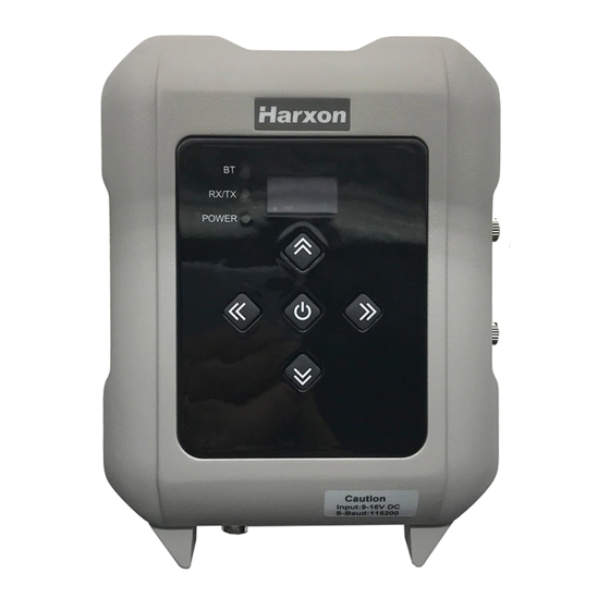
1 Introduction As a type of external transmitting-receiving data radio, eRadio supports many options of transmitting power, with waterproofing grade up to IP67 and sturdy and durable structure, applicable for outdoor use under all weather conditions. eRadio is equipped with 3 bi-color indicator lights (Wireless transmitting-receiving indicator light: green while receiving, red while transmitting;... -
Page 10: Product Features
1.1 Product Features Main features of eRadio: Full-band support, with the frequency point range of 410MHz -470MHz Many options of transmitting power Self-adaptive function of serial port baud rate OLED display 5 user buttons One-way RS232 interface ... -
Page 11: Interface And Component
2 Interface and Component 2.1 Interface of Serial Port Data Cable The interface of serial port data cable uses the asynchronous serial communication RS232 standard. Figure 2 Diagram of eRadio Data Interface Table 33 eRadio Data Interface Definition Description Remarks Power output DC9-16V Power Ground... -
Page 12: Bluetooth Module (Optional)
PWR/ALM is bi-color indicator light for normal power supply and under-voltage, green indicator light represents normal power supply, red indicator light represents abnormal voltage; 2.4 Bluetooth Module (Optional) If the current radio supports Bluetooth, users can configure and query the radio parameters by the means of Bluetooth, Bluetooth V4.0 is supported;... -
Page 13: Functions And Operation Instruction
3 Functions and Operation Instruction 3.1 Startup & Shutdown Button The startup & shutdown button (power button) can be used to control radio power-on and power-off, with specific functions as follows: Short press the startup button for about 1 second to power on, the green power indicator light illuminates in the case of successful power-on (under the condition of normal power supply). -
Page 14: Instruction Of Radio Startup And Power Indicator Light Conditions
If GPRS is re-connecting to the Corse station or server successfully, the red indicator light flickers five times in three second; Bluetooth led(green)is reserved. 3.6 Instruction of Radio Startup and Power Indicator Light Conditions Normal radio startup & shutdown has memory function, abnormal radio startup &... -
Page 15: Transmitting/Receiving Channel And Frequency
power, battery condition, device model, firmware version, hardware version and serial number are displayed. 3.7.2 Transmitting/Receiving Channel and Frequency In this menu column, you can set up the current transmitting/receiving frequency, select required communication frequency through up and down buttons, and press the OK key to select this frequency as the current communication frequency point, the character of“*”will appear after selection. -
Page 16: Rf Baud Rate
Note: After changing the protocol, you need reselect the RF baud rate supported by the current protocol in the menu of “wireless link rate”; 3.7.4 RF Baud Rate In this menu column, you can set up the current communication RF baud rate. Different protocols support different types of RF baud rates. -
Page 17: Serial Port Baud Rate
3.7.7 Serial Port Baud Rate In this menu column, you can set up the current serial port communication baud rate. Now, there are the following baud rates: 9600, 19200, 38400, 57600, 115200. Select required serial port communication baud rate through up and down buttons, and press the OK key to select this serial port communication baud rate as the serial port communication baud rate of the current communication, the character of“*”will appear after selection. -
Page 18: Oled Sleep Mode
3.7.9 OLED Sleep Mode Set up whether the OLED display enters sleep, only if the “Function” switch is in the “On” mode can the OLED display enter the sleep mode, sleep time has the following levels: 1min, 5min, 10min, 15min, 20min, 25min, 30min. ... -
Page 19: Language
3.7.11 Language Set up the display language of device fonts, Chinese and English are supported for this terminal. 3.8 Use of Radio Configuration Software Multiple forms of configuring radio parameters are supported. Users can change and query the current radio parameters by the means of background mode, user interface mode and PC configuration tool. -
Page 20: Configuration Tool Installation
Figure 3 Installation Instruction 3.8.2 Configuration Tool Installation Open the configuration tool installation file and click “Next” until installation is completed. In the end, one shortcut appears on the desktop. During the radio configuration later, you can directly open this shortcut to operate the radio, as shown in Figure Figure 4 Radio Query/Configuration Software Interface... -
Page 21: Radio Parameter Query
3.8.3 Radio Parameter Query Firstly, click “Read”, and select the right serial port number and the current operating radio serial port baud rate in the dialog box popped up, click “Connect” and “Read” in the end, now you can begin to read the radio configuration parameters. -
Page 23: Radio Parameter Configuration
3.8.4 Radio Parameter Configuration In the basic information column, only radio information can be queried, settings are not supported; In the channel information column, the frequency point range set up is signs„-‟ and „+‟can be used to increase between 410~470MHz, and delete or reduce. -
Page 24: Bluetooth App
In the personalization setting column, users can set up communication protocol, RF baud rate, serial port baud rate, transmitting power level and transmitting/receiving mode; In the power management column, users can set up the low-voltage alarm threshold value for radio operation and wireless data transmission voltage; ... -
Page 25: Configuration Tool"S Paring And Connection
3.9.2 Configuration Tool’s Pairing and Connection First, enter the Bluetooth parameters set by clicking “Bluetooth Set”. Then choose the need-to-pair Bluetooth name in “AVAILABLE DEVICES”. The default name of radio Bluetooth is the radio‟s serial number. Verification code is required for the first-time pairing, and the default verification code is 1234. After a successful pairing, the name of Bluetooth shall be displayed in the list of “PAIRED DEVICES”, and then just click the one which you want to connect with. -
Page 27: Radio Parameter Configuration And Query
3.9.3 Radio Parameters’ Configuration and Query When operator enters each functional module, there are two buttons regarding parameters: write and read. Clicking Read shall read out all parameters of the current functional module. When you finished the editing of parameters, please ensure the written parameter is incorrect, otherwise it will remind you “write failed”... -
Page 28: Firmware Upgrade
Power Manager Parameters in this module can be both read and written, including low voltage warning threshold and wireless data forbidden emission threshold. Network Set Parameters in this module can be both read and written. It is mainly about the parameters configuration in connecting with NTRIP Caster, including the setup of following items: Server Type, Server Address, Server Port, APN, Mountpoint, User-ID, Password, Agent。... - Page 29 3. Select right serial port number and baud rate, open the serial port and select internally installed radio, as shown in Figure Figure 5 Internally Installed Radio Firmware Upgrade Software Connection...
- Page 30 4. Select the file requiring upgrade (e.g.***.**.**F.dwn)
- Page 31 5. Click the “Begin to Update” button (when you click the “Begin to Update” button, one prompt dialog box pops up indicating whether a parameter is correct, now users are required to click OK; after that, the system enters into the upgrade condition immediately) 6.
-
Page 32: Appendix A Technical Indexes
Appendix A Technical Indexes A.1 Specifications and Parameters of Data Transmission Radio Table 4 Specifications and Parameters of Radio4 Overall Performance Specification Specification Name Specification Requirement Frequency Range 410~470MHz Operating Mode Transmitting-receiving, single transmitting, single receiving, radio relaying and network relaying Channel Interval 25KHz, 12.5KHz Modulation Mode... -
Page 33: Bluetooth Parameters
Receiver Performance Specification Specification Name Specification Requirement Sensitivity Superior than -115dBm@BER10 , 9600bps Adjacent Channel Selectivity >45dB@25KHz Stray Disturbance Resistance >45dB Modem Specification Name Specification Requirement RF Rate 4800bps/9600bps/19200bps Modulation Mode GMSK/4FSK A.2 Bluetooth Parameters Table 5 5Specifications and Parameters of Bluetooth Module Parameter List Value Remarks... -
Page 34: Eradio Suite Parts
A.4 eRadio Suite Parts A.4.1 Radio Configuration Cable (HJ394) (Optional) Figure 6 Structure and Dimension of External Data Transmission Radio Configuration Cable HJ394 Table 77 List of Radio Configuration Cable HJ394 Parts Mark Explanation Remarks Plug 1BHTN05P Rubber Coating Black Cable Black Cable... -
Page 35: Power Cable (Hj379)
Figure 8 HJ394 B Port Welding Surface View Table 88 Definition of HJ394 Data Cable B Port Name Description Remarks Output Input 1,4,6,7,8,9 Reserved Note: After connecting to the DB9 port on PC, this port can communicate normally. A.4.2 Power Cable (HJ379) Figure 9 Structure and Dimension of Power Cable HJ379... - Page 36 Table 9 List of Power Cable9 HJ379 Parts Mark Explanation Remarks Bullet Terminal 1 male connector and 1 female connector respectively Double-row cable Black a: Black alligator clip, b: Red alligator clip Fuse Support 1 male connector and 1 female connector respectively Fuse 32V/15A...
-
Page 37: Appendix B Command
Appendix B Command eRadio includes the following operating modes: Normal operating mode Background configuration mode Configuration tool configuration mode Upgrade firmware mode 1. Normal operating mode Under the normal operating mode, the radio can carry out data transmission;... - Page 38 4. Response format Ending Space Ending Command Query Result Character Character Character > For example, configure the current radio transmitting frequency point as 460.125Mhz: The format is shown as below: TX 460.0125\r\n; response format: \r\nPROGRAMMED OK \r\n> Query the current radio transmitting frequency point: The format is shown as below: TX\r\n;...
- Page 39 Command Command Format Response Format Explanation Name “transmitting frequency point is 456.05MHz; point” and “MHz” for separation; tx transmitting One space character is frequency point \r\n between the strings \r\nPROGRAMMED e.g.: Set up the PROGRAMMED and OK for OK\r\n> current separation;...
- Page 40 Command Command Format Response Format Explanation Name baud protocol \r\nPROGRAMMED type\r\n OK\r\n> RF baud e.g.: baud 9600\r\n Indicate the current rate setting Indicate setting up radio RF baud rate is the current radio RF written successfully baud rate as 9600 ...
- Page 41 Command Command Format Response Format Explanation Name between “SBAUD” and rate is 115200 “serial port baud rate” for separation; “serial port baud rate” has 6 characters in length, if the serial port baud rate currently displayed has less than 6 characters in length, use space characters to fill;...
-
Page 42: Appendix C Eradio Sim Setup
Appendix C eRadio SIM Setup... - Page 43 Appendix D eRadio FAQ Failure Description Cause Analysis Solutions If external power supply is used, connect to the power Unreliable power cable cable correctly, with the connection (external rated working voltage of power supply); DC12V; The positive and ...
Need help?
Do you have a question about the Harxon eRadio and is the answer not in the manual?
Questions and answers