
Related Manuals for Dynisco 1392 Series

Summary of Contents for Dynisco 1392 Series
- Page 1 1392 Series Temperature Indicator 1/8 DIN Temperature Indicator With Retransmission P/N 974143 REV 12/09 ECO# 35712...
-
Page 2: Table Of Contents
TABLE OF CONTENTS 1.0 QUICK START INSTRUCTION ..................3 1.1 Mounting ........................3 1.2 Wiring .......................... 3 1.3 Scaling ......................... 4 1.4 Instrument Configuration .................... 5 2.0 INTRODUCTION ......................6 2.1 Important Information ....................6 2.2 Copyright ........................6 2.3 Abbreviations ......................6 2.4 Features ........................ -
Page 3: Quick Start Instruction
1.0 QUICK START INSTRUCTION 1.1 Mounting • Prepare panel cutout to specified dimensions • Slide case through cutout and install mounting clips over case ends, engaging the detents in the case. Slide mounting clips fully forward (with the y side toward the front) until base is secure in panel. -
Page 4: Scaling
1.3 Scaling • Slide instrument out of case. While pressing the FUNC button, insert instrument back into case, continue to hold FUNC button until COnF is displayed. • Press FUNC once, then use the buttons to modify the units. • Press FUNC to modify the decimal point. -
Page 5: Instrument Configuration
1.4 Instrument Configuration • Remove the instrument from case. • Press and hold FUNC button while re-inserting instrument into case. • Continue to hold FUNC button.The display will show 1392, then the Software Version, then after 2 seconds, the display will show COnF. •... -
Page 6: Introduction
Following the safety instructions will help to prevent accidents, defects and malfunctions. DYNISCO will not be held liable for any injury, loss or damage resulting from failure to follow the instructions in this manual. If product malfunctions, in spite of having followed the operating instructions, please contact the DYNISCO customer service department (See the back of the manual for contact information). -
Page 7: Notes On Safety
Higher temperature can result in damage and malfunction. Do not install the indicator in places where this temperature is exceeded. DYNISCO will not be held liable for any injury, loss or damage resulting from failure to follow the instructions in this manual. -
Page 8: Technical Data
4.0 TECHNICAL DATA 4.1 Ordering Guide 1392-1-1 Dual Alarms with a 24Vdc Power Supply 1392-2-1 Dual Alarms and Analog Retrans with a 24Vdc Power Supply 1392-3-1 Dual Alarms and MODbus/JBus Comms with a 24Vdc Power Supply 1392-4-1 Dual Alarms, Analog Retrans and MODbus/JBus Comms with 24Vdc Power Supply 1392-1-3 Dual Alarms with a 85 to 264Vac Power Supply... -
Page 9: Linear Input Specifications
Normal Mode Rejection: 60 dB at 50 or 60 Hz Accuracy: Volt range: +/- (1 mV + 0.25% of measurement) mA range: +/- (250 µA + 0.25% of measurement + shunt resistor accuracy) Temperature Drift: Less than 200 ppm Power Supply Options: 85 to 264Vac or 24Vac or dc, -15% +20% Operating Altitude: up to 2000 meters... -
Page 10: Special Features
Open Circuit Detection: On 4 - 20mA by downscale fault On 0 - 5Vdc, 1 - 5Vdc, 0 - 10Vdc, 2 - 10Vdc by AC lead impedance measurement Input Selection: Internal according to instrument configuration Input Resolution: Adjustable by 1 up to 10000 Adjustable by 10 from 10000 to 99900 Decimal point may be set in any position Measurement Resolution:... -
Page 11: Serial Communications Interface
4.2.5 Serial Communications Interface Type: RS-485 Isolation: Isolated (reinforced insulation) from instrument and all other I/O circuits. Protocol: MODbus and JBus Baud Rate: 150 to 19200 baud Format: 8 bits + parity 8 bits without parity Parity : Odd/Even 4.2.6 Analog Retransmission Output Types: 0 - 20mA or 4 - 20mA, max load 500R 0 - 5Vdc or 0 - 10Vdc, keyboard selectable... -
Page 12: Description
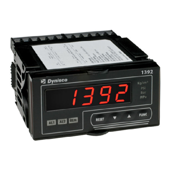
5.0 DESCRIPTION The Dynisco model 1392 Linear Input Indicator is a flexible, programmable indicator designed for analog sensors. The five digit, 0.52” LED display provides a precise, readable indication of the measured value. You can program the 1392 to display °C, °F, or None up to a Full Scale Value (F.S.U.) of 99,900 with an accuracy of ±... -
Page 13: Transport & Delivery
• Do not let the indicator be damaged by other items during transit. • Use only the original packaging. • Report transport damage to DYNISCO immediately in writing. 6.2 Storage • Store the indicator in original packaging only. • Protect against dust and moisture. -
Page 14: Installation
7.0 INSTALLATION 7.1 Unpacking Inspect the package for shipping damage. If you notice any damage, notify the freight carrier immediately. 7.2 Unit Mounting Fig 7-2 Panel Cutout • Make the instrument panel cut-out with the specified cut out dimensions. o 1.77 +0.03/-0” high (45 +0.8/-0mm) x 3.62 +0.03/-0” wide (92 +0.8/-0 mm) •... -
Page 15: Start-Up
8.0 START-UP 8.1 Set-Up 8.1.1 Front Panel The front of the Model 1392 is shown here. Key items on the front panel are: • A five digit LED display • LED indicators AL1 (Alarm 1) and AL2 (Alarm 2) • LED indicator REM (Remote Status) •... - Page 16 then press and hold the second pushbutton, and then press the third pushbutton, if required. Note: You must follow the pushbutton sequences exactly as described. 8.1.3 Rear Terminal Connections The electrical connections for the Model 1392 are shown. The layout of the terminals, is depicted from the rear.19 COMMISSIONING Fig 8.1.3-1 Fig 8.1.3-2...
- Page 17 Fig 8.1.3-4 8.1.4 Configuration, Calibration Mode To enter the configuration mode, hold the FUNC button while powering the unit on until COnF is displayed. A list of all configuration parameters starts. • Press FUNC to initiate the configuration procedure, starting at the first parameter. •...
- Page 18 Display Units “Un” This parameter selects the temperature unit to display Selections: °C or °F or Off = None Default: °C Decimal Point Position “_ _ _ _ . _ ” This parameter selects the decimal point position Selections: _ _ _ _ _ for no digits after the decimal point _ _ _ _ .
- Page 19 External Contact Function “ EC ” This parameter selects the External Contact. to enable external contact for manual alarm reset, via rear digital input terminals Ho to enable external contact for hold-on-value sampling Default: nr Alarm Manual Reset Contact Status “ C5 ” This parameter selects the Contact Status CL if function selected above is performed with contact closed, or OP if function selected above is performed with contact open.
- Page 20 Alarm 2 Operating Mode “ A2 ” This parameter selects Alarm 2 status Follow the same procedure as in steps F4 above. Default: High with Automatic Reset Serial Communications Protocol (Option) This parameter selects the optional serial communications protocol NbUS for Modbus protocol JbUS for Jbus protocol Analog Output ( Option ) Analog Output type “...
- Page 21 Default: 19200 Serial Communication Byte Format “ bF ” This parameter establishes the serial communication byte format 8E for 8 bits with even parity 8O for 8 bits with odd parity for 8 bits with no parity Default: no parity Note: The configurator skips this section if serial communication is NOT implemented.
- Page 22 8.1.6 Input Calibration Note: Input calibration not required since unit is factory calibrated. Do not attempt unless unit requires calibration. Place the indicator in CAL mode by pressing and holding down the FUNC button while powering up the unit. When the indicator shows COnF, press the UP arrow once to show CAL on the display.
- Page 23 8.1.7 Analog Output Calibration Place the indicator in CAL mode by pressing and holding down the FUNC button while powering up the unit. When the indicator show COnF, press the UP arrow once to show CAL on the display. Press the FUNC button until the appropriate C parameter is displayed. Connect a multimeter to DC Out + and DC Out -.
- Page 24 The codes for the remaining digits in the alarm-operating mode are: 2nd Digit 3rd Digit 4th Digit 5th Digit H = High Alarm A = Automatic reset d = Direct action n = Low alarm mask L = Low Alarm n = Manual reset r = Reverse action blank = Not masked For example, a display of I.HAr would indicate High alarm, automatic reset, reverse action.
- Page 25 8.3 Default Data Loading Procedure In each one of the Indicator’s three modes, configuration, calibration and operation, you can load default data to reset all of the parameters for that particular mode. To load the default data: Press + , and once the display shows dF OFF, press . When the display shows dF On, press FUNC.
-
Page 26: Troubleshooting & Error Messages
This error message disappears automatically after 3 seconds, and the instrument will reset. If the error persists, return the instrument to Dynisco. If this error appears during configuration/calibration, press FUNC or RESET to restart the procedure and then repeat operations. If error persists, return the instrument to Dynisco. - Page 27 Error during internal autozero measurement for temperature drift compensation. The instrument repeats this check every 3 seconds. The analog retransmission and alarm go low scale or high scale as a fail safe configuration. If the error persists, return the instrument to Dynisco. Er313 Calibration data fails checksum.
- Page 28 Er317 Instrument non-volatile memory un-initialized. Return to Dynisco. Er900 ROM error. Return to Dynisco. Er901 RAM error. Return to Dynisco. Er902 Key stuck detected. Check domed buttons for damage. Er903 CPU fault. Return to Dynisco. ooooo Over-range indication. This status is displayed when the A/D converter value is out of range, or the input signal is greater than full scale value plus 27% of span, or the displayed value exceeds the display capability of 99900.
-
Page 29: Ce Declation Of Conformaty
10.0 CE DECLATION OF CONFORMATY... -
Page 30: Modbus & Jbus Communications
11.0 MODBUS & JBUS COMMUNICATIONS 12.1 Introduction……………pg 31 12.2 Transmission Format....pg 31 12.3 Communication Procedure....pg 32 12.4 Error Check (CRC-16 Cyclical Redundancy Check……………pg 33 12.5 Function Code 3 & 4: Words Reading……………pg 33 12.6 Notes……………pg 35 12.7 Error Codes……………pg 37 12.8 Operative Mode Addresses……………pg 38 12.1 Introduction This half duplex protocol accepts one master and one or more slaves. -
Page 31: Communication Procedure
12.3 Communication Procedure The communication can be initiated only by the master unit; the slave units can transmit only after a query has been received from the master. The general format for the transmission from master to slave is the following: Range Byte Slave address... -
Page 32: Error Check
3. Shift the CRC-16 register one bit to the right (toward the LSB), zero-filling the MSB. Extract and examine the LSB. (If the LSB was 0): Repeat Step 3 (another shift). (If the LSB was 1): Exclusive OR the CRC-16 register with the polynomial value A001h (1010 0000 0000 0001b). - Page 33 Request from Master to Slave Range Byte Slave address (1-255) Function code (03-04) Word starting address (high byte) Word starting address (low byte) Number of word (high byte) Number of word (low byte) Error check (CRC-16) (low byte) Error check (CRC-16) (high byte) Reply from Slave to Master Range Byte...
-
Page 34: Notes
Request from Master to Slave Range Byte Slave address Function code Word starting address (high byte) Word starting address (low byte) Number of words (high byte) Number of words (low byte) Error check (CRC-16) (low byte) Error check (CRC-16) (high byte) The 6 bytes in “Data”... - Page 35 Variable Value Meaning Number without decimal digit Number with one decimal digit Number with two decimal digits Number with three decimal digits Number with four decimal digits 5. Multiplier Same parameters have a related variable stated as “multiplier”; this system allows to overcome the limits of +/- 32767 counts.
-
Page 36: Error Codes
9. Address Space The whole variables are addressable as word as well as bit; the user may choose the better way according to the condition. Although common sense suggests managing analog variables as words and boolean variables as bits, below is described the behavior to access analog variables (example: alarm threshold) as bits and boolean variables (example: local/remote device status) as words. -
Page 37: Operative Mode Addresses
12.8 Operative Mode Addresses Jbus MODbus Description Display Attribute Address Address Code Manufactured trade mark Range: 50 (32h) Device identification code Note: Nr. of software revision x 100 + identification code (1309h for 1390) Reserved RDM Filtered input variable RDM Notes: When an error is detected on measure, the”Data field”... - Page 38 Jbus MODbus Description Display Attribute Address Address Code Status alarm 2 R Range: 0 = No alarm 1 = Alarm *131 Alarm 1 threshold RWDM *132 Alarm 2 threshold RWDM Input variable without filter RDM Notes: When an error is detected on measure, the”Data field”...
- Page 39 Jbus MODbus Description Display Attribute Address Address Code Tare calibration (“tARE”) Range: 0 = Disable calibration 1 = Enable calibration Last calibration status Range: 0 = Idle 1 = calibration in progress 3 = calibration done without error 4 = calibration done with error Notes: After reading, the word is set to 0 if the value read is 3 or 4.
- Page 40 Jbus MODbus Description Display Attribute Address Address Code Decimal point position Range: 0 = No decimal figure 1 = One decimal figure 2 = Two decimal figures 3 = Three decimal figures 4 = Four decimal figures Note: Decimal figure assigned to: - Initial scale readout - Final scale readout - Input variable without filter...
- Page 41 Jbus MODbus Description Display Attribute Address Address Code Input fail safe (“I.F.S”) Range: 0 = Down scale burn out (Lo) 1 = Up scale burn out (Hi) External contact function (“E.C.”) Range: 0 = Enable external contact for manual alarm reset (nr) 1 = Enable external contact for stop on measuresampling (Ho) Contact status (“C.S.”)
- Page 42 Jbus MODbus Description Display Attribute Address Address Code Alarm 1 filter (“A1”) Range: 0 = No Filter on alarm threshold (OFF) 1 = Filter on alarm threshold (On) see ModBus address word 261 Alarm 1 hysteresis (“H1”) Number of decimal figures related to: R Alarm 1 hysteresis Alarm 2 operative modeRange: (“A2”)
- Page 43 Jbus MODbus Description Display Attribute Address Address Code Serial communication baud rate (“bd”) Range: 0 = 9600 Baud 1 = 19200 Baud 2 = 150 Baud 3 = 300 Baud 4 = 600 Baud 5 = 1200 Baud 6 = 2400 Baud 7 = 4800 Baud Serial communication byte format (“bF”) Range:...
-
Page 44: Warranty & Service
Please call for a Return Material Authorization Number before returning product to Dynisco. Questions concerning warranty, repair cost, and delivery should be directed to the Dynisco Repair Department, telephone number 508-541-9400 or E-mail: repair@mc.dynisco.com. For further technical assistance, call 800-221-2201...
Need help?
Do you have a question about the 1392 Series and is the answer not in the manual?
Questions and answers