Summary of Contents for Mako Networks 6000 Series
- Page 1 Mako Networks Quick Installation Guide For Petroleum Sites with Mako Performing Verifone Zone Router Function February 2020 v2.1.1...
-
Page 2: General Information
General Information Please utilize this documentation along with any Verifone-published brand/major oil specific documentation. Note: Not all brands will require additional documentation. The Mako appliance being installed at this location connects to the internet and creates up to four physically separated network subnets; Card Net, VFI POS, Store and Open/Outside EMV. Whilst the Mako appliance will work with either a public or a private IP address, it requires unfiltered access to the internet. - Page 3 For assistance if you experience any difficulties with the installation please contact Mako Networks: Mako Installer Support Number: 844 807 0307 (24x7) A few points to note during installation: 1) Technician MUST have the following tools available for the Mako installations: a.
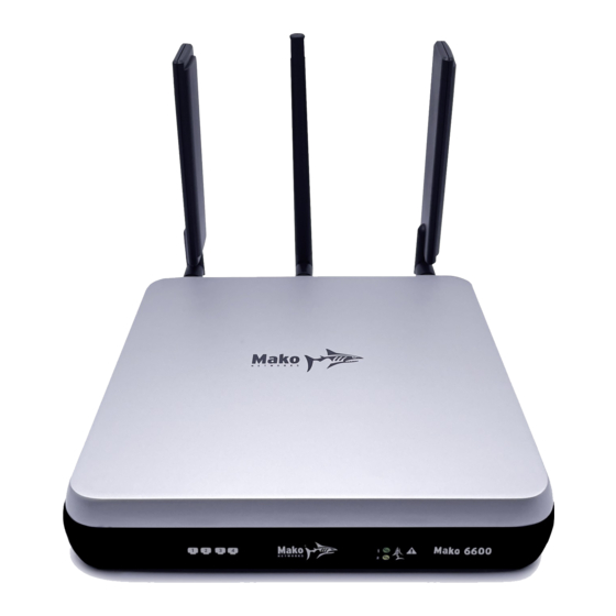
- Page 4 Basic Mako Installation 1) Arrive on site at the designated start time. 2) Unbox the Mako appliance. 3) Connect cellular and WiFi antennas. The broad paddle antennas are the cellular antennas and the thin round antenna is the WiFi antenna. Please note the antenna connectors are sexed to ensure correct antenna placement.
-
Page 5: Installation Scenarios
Installation Scenarios Type 1: New Install, No Outside EMV 1) LAN 1 (Card Net) should be cabled to slot A on the Commander or the Payment Network port on the Commander 16/RubyCi. 2) LAN2 (VFI POS) connects to the Mako-supplied switch. The Verifone POS and Verifone Zone port (N on the Commander and Ethernet Symbol on Commander 16/RubyCi) will connect to the Mako- supplied switch. - Page 6 Type 2: New Install with Outside EMV generic 1) LAN 1 (Card Net) should be cabled to slot A on the Commander or the Payment Network port on the Commander 16/RubyCi. 2) LAN2 (VFI POS) connects to the Mako-supplied switch. The Verifone POS and Verifone Zone port (N on the Commander and Ethernet Symbol on Commander 16/RubyCi) will connect to the Mako- supplied switch.
- Page 7 Type 3: New Install with Outside EMV with Wayne dispensers 1) LAN 1 (Card Net) should be cabled to slot A on the Commander or the Payment Network port on the Commander 16/RubyCi. 2) LAN2 (VFI POS) connects to the Mako-supplied switch. The Verifone POS and Verifone Zone port (N on the Commander and Ethernet Symbol on Commander 16/RubyCi) will connect to the Mako- supplied switch.
- Page 8 Network layout with Wayne Anthem dispensers with wired ethernet: M A K O 6 0 0 0 S E R I E S LAN 1 LAN 2 LAN 3 LAN 4 UNMANAGED SWITCH VERIFONE BACK OFFICE PINPAD PINPAD COMMANDER MAKO LAN 4 MEDIA GATEWAY ANTHEM EDGE...
- Page 9 Network layout with Wayne Anthem dispensers with wireless: M A K O 6 0 0 0 S E R I E S LAN 1 LAN 2 LAN 3 LAN 4 UNMANAGED SWITCH VERIFONE BACK OFFICE PINPAD PINPAD COMMANDER MAKO LAN 4 WI-FI MEDIA GATEWAY ANTHEM EDGE...
- Page 10 Type 4: Upgrade to Mako with existing EZR, No Outside EMV 1) LAN 1 (Card Net) should be cabled to slot A on the Commander or the Payment Network port on the Commander 16/RubyCi. 2) LAN2 (VFI POS) should be cabled according to one of two scenarios: a.
- Page 11 Type 5: Upgrade to Mako with existing EZR and with Outside EMV generic 1) LAN 1 (Card Net) should be cabled to slot A on the Commander or the Payment Network port on the Commander 16/RubyCi. 2) LAN2 (VFI POS) should be cabled according to one of two scenarios: a.
- Page 12 Type 6: Upgrade to Mako with existing EZR and with Outside EMV with Wayne dispensers 1) LAN 1 (Card Net) should be cabled to slot A on the Commander or the Payment Network port on the Commander 16/RubyCi. 2) LAN2 (VFI POS) should be cabled according to one of two scenarios: a.
- Page 13 Network layout with Wayne Anthem dispensers with wired ethernet: M A K O 6 0 0 0 S E R I E S LAN 1 LAN 2 LAN 3 LAN 4 CYBERA ZONE ROUTER VERIFONE BACK OFFICE PINPAD PINPAD COMMANDER MAKO LAN 4 MEDIA GATEWAY...
- Page 14 Network layout with Wayne Anthem dispensers with wireless: M A K O 6 0 0 0 S E R I E S LAN 1 LAN 2 LAN 3 LAN 4 CYBERA ZONE ROUTER VERIFONE BACK OFFICE PINPAD PINPAD COMMANDER MAKO LAN 4 WI-FI MEDIA GATEWAY...
-
Page 15: Final Checkout
Final Checkout 1) Before checking out, visually recheck the front panel of the Mako appliance: POWER INTERNET Wireless LANs ERROR If all is operational the Power, Internet, WAN and CMS LEDs should all be illuminated in GREEN as well as LANs 1 and 2. In some instances, the Wireless LED may also be GREEN if implementing VFI Mobile Self Checkout.


Need help?
Do you have a question about the 6000 Series and is the answer not in the manual?
Questions and answers