Table of Contents
Advertisement
Advertisement
Table of Contents

Summary of Contents for Hoppecke Electrolyte Circulation System
- Page 1 Installation and Operating Instructions Electrolyte Circulation System...
- Page 2 All rights reserved, even for patent and utility patent applications. The distribution and duplication of this document and the use and disclosure of its contents are prohibited unless written permission is granted by HOPPECKE Batterien GmbH & Co. KG. Noncompliance will result in a claim for damages.
-
Page 3: Table Of Contents
Step 5: Install current sensor ......................15 Step 6: Connect power supply ......................17 Operation ............................. 21 Connection terminals ..........................22 Error states ............................22 Maintenance ............................22 Technical Data ............................23 Annex A: References ..........................24 Electrolyte Circulation System 7145240031 V1.1 (01.2013) -
Page 4: Preface
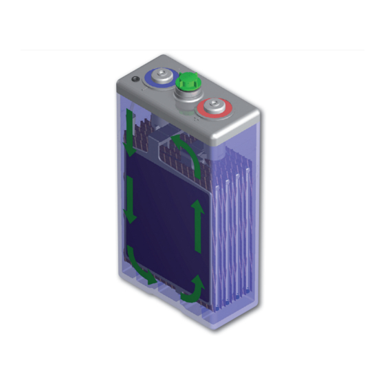
Preface The HOPPECKE Electrolyte Circulation System pumps ambient air to the bottom of each battery cell. Emerging air bubbles rise through the electrolyte, ensuring a homogeneous electrolyte den- sity distribution in each battery cell. The HOPPECKE Electrolyte Circulation System provides several important benefits: •... -
Page 5: Safety Precautions
Safety precautions Incorrect use of the product described here can lead to personal and material damage. HOPPECKE is not responsible or liable for direct or indirect personal and material damages which occur as a result of handling the products described here. -
Page 6: Required Parts And Tools
Ohm and an insulation resistance of ≥10 (refer EN 50272-2 and DIN EN ISO 20345:2011 Personal protective equipment – Safety footwear). Refer also to the HOPPECKE manual “Installation, commissioning and operating instructions for vented statio- nary lead-acid batteries” (refer to /1/). -
Page 7: Parts Of Delivery
Connection Cables for power supply (1.5 mm and 6 mm 2x Cable lugs for 6 mm power supply cable 2 x Wire termination (6 mm ) for power supply cables 4 x Wire strips Electrolyte Circulation System 7145240031 V1.1 (01.2013) -
Page 8: System Overview
Note: For 48V battery systems with larger cells (18 OPzS solar.power 3250 up to 26 OPzS solar.power 4700) two electrolyte circulation pumps are required (refer to Figure 5). Figure 2: Pump and control unit Figure 3: Schematic diagram Electrolyte Circulation System 7145240031 V1.1 (01.2013) - Page 9 Figure 4: System overview - Components Figure 5: System setup for 48V battery systems with cells >= 18 OPzS solar.power 3250 (18 OPzS solar.power 3250 up to 26 OPzS solar.power 4700) Electrolyte Circulation System 7145240031 V1.1 (01.2013)
-
Page 10: Installation
Any recombination system plugs need to be replaced by the HOPPECKE Labyrinth plugs (refer also to /3/). • Please contact your HOPPECKE representative in case you want to use the Electrolyte Circulation System together with an automatic water refill system. - Page 11 When finished the head of the air tube is located 1 to 2 cm beneath the end of the electrode plate sets (refer also to Figure 6). 4. Mount the plastic T-junctions on top of the hard plastic tubes. Figure 8: T-junction and rubber insert Figure 9: Hard platic tube Electrolyte Circulation System 7145240031 V1.1 (01.2013)
-
Page 12: Step 2: Connect All Air Tubes
Note: Make sure that all tubes are connected closely so that no air is leaking out of the system during pump operation. Figure 10: Connection between air tubes - I Figure 11: Connection between air tubes - II Electrolyte Circulation System 7145240031 V1.1 (01.2013) -
Page 13: Step 3: Mount The Pump- And Control Unit
(soft) air tube, the cable length of the current sensor and the cable length of the power supply cable (refer also to Figure 4). This distance is about 3m max. Figure 12: Installation of pump- and control unit Electrolyte Circulation System 7145240031 V1.1 (01.2013) -
Page 14: Step 4: Connect Air Tube To The Pump And Control Unit
The master pump activates / deactivates the slave pump via a control wire (refer to Figure 5). Figure 13: Connect air tubing to pump- and control unit Figure 14: Connection of back pressure value Electrolyte Circulation System 7145240031 V1.1 (01.2013) -
Page 15: Step 5: Install Current Sensor
• The arrow printed on the current sensor must show towards the charging device (refer to Figure 16). • The label “This side high sensibility / sensitivity” typically faces towards the battery cable. Figure 15: Attachment of the current sensor Figure 16: Arrangement of current sensor Electrolyte Circulation System 7145240031 V1.1 (01.2013) - Page 16 (refer to Figure 18 and Figure 19). Figure 19: Connection terminal for current sensor Figure 19: Connection terminal for current sensor Copyright HOPPECKE Batterien GmbH & Co. KG, version: V1.0 (Apr 10 2012) 14/22 All details in this document are based on state-of-the-art technology.
-
Page 17: Step 6: Connect Power Supply
5mm threat (M5) on top of the terminal connection bolt with the provided 5mm screws. 14. Put the provided plastic covers onto the battery terminal connection bolts for touch protec- tion. Electrolyte Circulation System 7145240031 V1.1 (01.2013) - Page 18 Figure 21: Connection terminal for power supply Figure 21: Connection terminal for power supply Figure 22: Power supply connection – Battery terminal connection bolt Copyright HOPPECKE Batterien GmbH & Co. KG, version: V1.0 (Apr 10 2012) 16/22 Figure 22: Power supply connection - Battery terminal connection bolt All details in this document are based on state-of-the-art technology.
- Page 19 Figure 24: Fuse holder connection Figure 25: Terminal connection bolt and plastic cover Figure 25: Terminal connection bolt and plastic cover opyright HOPPECKE Batterien GmbH & Co. KG, version: V1.0 (Apr 10 2012) 17/22 details in this document are based on state-of-the-art technology.
- Page 20 Slave Current sensor Figure 27: Master slave configuration Figure 27: Master slave configuration Copyright HOPPECKE Batterien GmbH & Co. KG, version: V1.0 (Apr 10 2012) 18/22 All details in this document are based on state-of-the-art technology. Our products are subject to constant development. We therefore reserve the right to make changes.
-
Page 21: Operation
Operation The HOPPECKE Electrolyte Circulation System recognizes via the current sensor whether the battery is charged or discharged. Only during battery charging operation the pump control unit will switch the pump on for a certain interval. During pump operation ambient air is filtered and passed to the air outlet nozzle. The air stream is then directed via air tubes to the bottom of every single battery cell. -
Page 22: Connection Terminals
60 °C. Table 1: Error states Maintenance The pump motor and the control unit of the Electrolyte Circulation System are maintenance free. However HOPPECKE recommends replacing the air intake filter every year. Electrolyte Circulation System 7145240031 V1.1 (01.2013) -
Page 23: Technical Data
Figure 30: Dimensions of pump- and control unit mensions in mm (refer to Figure 30). Dimensions in mm (refer to Figure 30). pyright HOPPECKE Batterien GmbH & Co. KG, version: V1.0 (Apr 10 2012) 21/22 details in this document are based on state-of-the-art technology. -
Page 24: Annex A: References
Table 2: Assignment of air tubes to battery cells Annex A: References The following tables contain the length of the lead electrode for various HOPPECKE battery cells. /1/ “Installation, commissioning and operating instructions for vented stationary lead-acid batteries”, Copyright HOPPECKE Batterien GmbH & Co. KG, Mar 2009 /2/ “OPzS solar.power Charging Procedure”, Copyright HOPPECKE Batterien GmbH &... - Page 25 Notizen: Electrolyte Circulation System 7145240031 V1.1 (01.2013)
- Page 26 Notizen: Electrolyte Circulation System 7145240031 V1.1 (01.2013)
- Page 27 Notizen: Electrolyte Circulation System 7145240031 V1.1 (01.2013)
- Page 28 Installation and Operating Instructions Electrolyte Circulation System HOPPECKE Batterien GmbH & Co. KG Phone +49(0)2963 61-0 Email info@hoppecke.com P.O. Box 1140 · D-59914 Brilon Bontkirchener Straße 1 · D-59929 Brilon-Hoppecke +49(0)2963 61-270 www.hoppecke.com...
Need help?
Do you have a question about the Electrolyte Circulation System and is the answer not in the manual?
Questions and answers