Table of Contents
Advertisement
Advertisement
Table of Contents

Summary of Contents for KLC Disco 240
- Page 1 Scanner control console User’s Manual...
-
Page 2: Table Of Contents
Table of contents Parameters…………………………………………………..………..1 Safety use cautions…………………………………………………….2 Contents in the package………………………………………………..2 Communication cable…………………………………………..…...…2 DMX512 address distribution……………………………………….…3 Diagram of the communication cable link and scanner address set…...4 Diagram of the panel and functional areas……………………….……5 Explanation of functional area of the panel………………………..…..5 Explanation of the duplex key area…………………………………….7 10. -
Page 3: Parameters
Thanks for using Disco240 scanner console! Disco240 console has internationally standard DMX512 signal output. Before operation,pl ease refer to the user’s manual carefully. 1. Parameters Output signal specifications DMX512 international standard Total number of channels 192 channels Number of scanners 24 scanner Max. -
Page 4: Safety Use Cautions
2. Safety use cautions The console must be connected to the safety earth line. Never pulling out or inserting the communication cable with electricity. Start order:Please turn on all the controlled scanner power suppies first,and then turn on the controller power,otherwise the controller is easy to be destr Oyed. -
Page 5: Dmx512 Address Distribution
5. DMX512 address distribution Disco240 console uses 1 to 240 channels of DMX512,so it can control the scanners with no more than 16 channels. The address is distributed as follows: Scanner DMX starting address Scanner serial number When using Disco240 Decimal system Scanner address switch location 1 ON... -
Page 6: Diagram Of The Communication Cable Link And Scanner Address Set
6.Diagram of the communication cable link and scanner addree dial Terminal resistance: 120ohms/1W No.12 Scanner: Disco 240 Scanner control console No.8 Scanner: No.7 Scanner: No.6 Scanner: No.5 Scanner: No.4 Scanner: No.3 Scanner: No.2 Scanner: No.1Scanner:... -
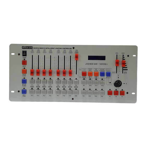
Page 7: Diagram Of The Panel And Functional Areas
8.Explanation of functional area of the panel Serial Name description Function explanation Numbe Controller internal mains switch; if the power supply of POWER the whole machine needs to be turned off , please pull out the external power adaptor. Change the light converting and operation state LED is on: light converting,all the output DMX BLACK signals are 0. - Page 8 In the program state, press this key area once, and the chase number to be edited is selected; press this key area again, and the scanner to be controlled is selected. When running the program, it is used to call out the edited chase number.
-
Page 9: Explanation Of The Duplex Key Area
9. Explanation of the duplex key area In program state, it is used to delete the chase or chase step, and cancel the setup of the transfer channel. Instantly press down: Delete the current chase step. [DELETE] Press down for 3 seconds: Delete the current chase step, and make it an empty program. -
Page 10: Explanation Of The Display Information On The Lcd
10. Explanation of the display information on the LCD Display Specific information Company name, model and version number DISCO 240 V3.0A S/N:0020-02-2727**** Sequence Number and test condition TEST Press [EDIT/RUN], the corresponding indicating light will be off, indicating the console is in the running standby. -
Page 11: The Editing Of Scanner Chase
or CROSS [***] Press[EDIT/RUN], to have the corresponding indicating light on, indicating the console is in the edit state. The ?? in Chase[??] represents edited chase number to be run. EDIT Chase [??] STEP [01] is the serial number of the chase step, which can change STEP [01] [**] with the operation of [... -
Page 12: Running Of Scanner Chases
to be edited, which is shown in Chase [ ] on the LCD. The press numbers (P1-P12), to select the controlled scanner, and its corresponding LED will be on. If the corresponding indicating light is not on, then that scanner has been selected, so it will not be affect by Step 5. 5. -
Page 13: Special Scene Presentation
potentiometer is in the bottom AUTO area, then the chase pause time and chase cross time that had already been edited will be run. 4. Press [CROSS MODE], to change the running mode; see 9.explanation of the duplex key area for details. 5. -
Page 14: Conventional Dimmer Control
14. How to set and cancel the rocker potentiometer Set the rocker potentiometer settings: Press [RUN/EDIT], to light the indicating light, and then press [SET X/Y] immediately; according to the prompt on the LCD, select two scanning channels corresponding to the scanner X and Y direction from (P1-P8) (or from PCH9-PCH16 by pressing SHIFT), shift to use the rocker potentiometer to control the green indicating light, and the light is on immediately.
Need help?
Do you have a question about the Disco 240 and is the answer not in the manual?
Questions and answers
I want to remove manual set x/y
To remove the manual set X/Y on a KLC Disco 240:
1. Enter the [SET X/Y] state.
2. Press [DELETE] to clear the input data; the green indicating light will turn off.
3. Press [SET X/Y] again to save the change and exit.
This answer is automatically generated