Table of Contents
Advertisement
Quick Links
Advertisement
Table of Contents

Summary of Contents for Fancom FaroTek
- Page 2 N.B.: The original, authentic version of this manual is the English version produced by Fancom B.V. or one of its daughter companies (referred to further as Fancom). Any modifications introduced to this manual by third parties have neither been checked nor approved by Fancom. Modifications are taken by Fancom to include translations into languages other than English and the insertion and/or deletion of text and/or illustrations to/from the original contents.
-
Page 3: Table Of Contents
Connect the dispenser to the drop pipe ..................8 Connect the dispenser to the conveyer pipe ................... 9 Label each FaroTek dispenser with the desired FaroTek pen number ......... 10 Install the TouchTek box and TouchTek server ................11 Install the FaroTek power packs ....................12 Connecting the parts of the FaroTek system .................. -
Page 4: Fancom Sales & Service Center
FaroTek TouchTek PC + server manual Milan-Touch handterminal manual Please read these manuals in this order. The FaroTek Installation manual is relevant for installation staff and not relevant for the end users. The following symbols are used in this manual: Tips and suggestions. - Page 5 The guarantee will not apply if this product is used in any way other than that indicated by Fancom. Never install a damaged FaroTek! Notify your supplier of any damages. Disconnect power before installation or before carrying out any maintenance to the control computer.
-
Page 6: System Overview
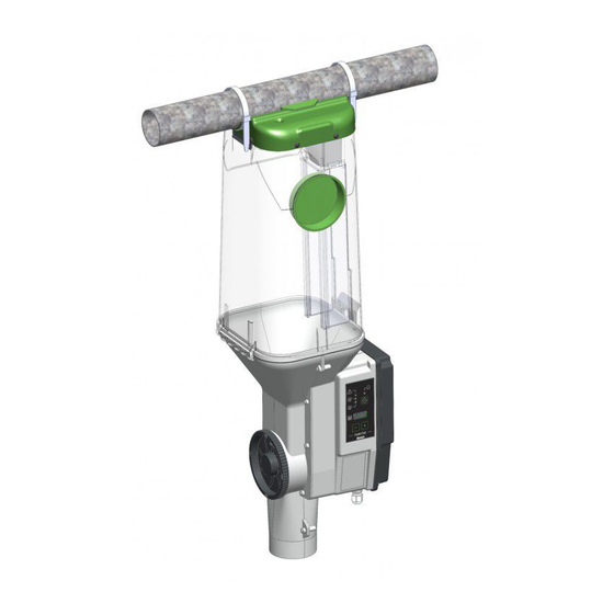
The FaroTek dispenser will be installed in an individual sow pen (e.g. a farrowing pen). The sow can trigger the push sensor for a feed request. The FaroTek will dispense a portion of feed as long the sow has an open feed demand. - Page 7 FaroTek System overview TouchTek box All FaroTek dispensers (max. 64) in one section are controlled by a TouchTek box. The TouchTek box has a color touchscreen that displays important information about the sows in the section and that can be used to edit settings.
-
Page 8: Connect The Push Sensor To The Drop Pipe
FaroTek System overview To install and connect the complete FaroTek system you have to install and connect the components in the following order: Task Page Check Install the parts of the FaroTek system Connect the push sensor to the drop pipe... - Page 9 60/75mm. If the feed pipe diameter is out of this range, please contact the dealer or Fancom. The connected feed conveyer will not be controlled by the FaroTek system. Please make sure that the feed conveyer is configured on a way that (during feeding time) no FaroTek dispenser will be out of feed.
- Page 10 FaroTek Installing the parts of the FaroTek system Widen the hole in the other direction, as shown in the illustration. Feed in the end of the push ball sensor cable as shown in the illustration. Let the push ball sensor slide through the drop pipe.
- Page 11 Don’t put the drop pipe too deep into the trough to avoid water entering the pipe. In that case the pipe could be blocked by wet feed. Option A If possible connect the FaroTek dispenser (3) direct to the drop pipe (1) using a HT-fitting (2).
- Page 12 Option B If it is not possible to connect the FaroTek dispenser (3) straight above the drop pipe (1) you have to use a flex hose (2). Cut the flexible hose (2) to the relevant length and place the flexible hose on the drop pipe (1) and on the FaroTek dispenser (3).
- Page 13 FaroTek Installing the parts of the FaroTek system Give every FaroTek pen of a FaroTek section a unique FaroTek pen number. Label each FaroTek dispenser with the corresponding FaroTek pen number.
- Page 14 FaroTek Installing the parts of the FaroTek system Mount the TouchTek box near to the section where the operator has easy and quick access. Mount the TouchTek server near to the PC. The Ethernet cable between the TouchTek server, TouchTek box, and PC should not exceed 100 meters in length.
-
Page 15: Install The Farotek Power Packs
Consider the maximal cable length of 50m between the FaroTek power pack and the last FaroTek dispenser you want to connect! The FaroTek power pack unit has to be assembled out of the reach of the animals. It is advisable to fasten it to the feed conveyer pipe. -
Page 16: Connecting The Parts Of The Farotek System
By routing and connecting the electrical wiring, please consider the “general instructions about cable connections” as described at appendix “Cable routing” (see). The FaroTek dispensers are operated at low voltage (24V DC). Power is supplied through decentral, individual FaroTek power packs for a maximum of 8 FaroTek dispensers. - Page 17 (2). If there are other FaroTek dispensers to be connected to this FaroTek power pack, then route a bus cable from this FaroTek dispenser (3) to the next one until all FaroTek dispensers of this FaroTek power pack are connected to a bus cable (max. 8 FaroTek dispensers per FaroTek power pack!).
- Page 18 Wire Connection 115V / 230V: From previous FaroTek L (black) power pack N (blue) PE (green/yellow) 115V / 230V: To the next FaroTek power L (black) pack N (blue) PE (green/yellow) PioNet: Slave bus IN connector from Minus (green) TouchTek box / previous FaroTek power...
-
Page 19: Connect The Farotek Dispensers
Provide electrical power to the FaroTek power packs by routing a suitable power cable (1 & 2). Protect the FaroTek power packs Close the cover of the FaroTek power pack and make sure that the gasket as well as the cable glands are properly positioned to prevent dirt and moisture from entering the housing. - Page 20 FaroTek Connecting the parts of the FaroTek system Overview TouchTek box cables Nbr. Cable Wire Connection Power input (115/230V) Terminal L Terminal N Terminal PE Ethernet 1 from the TouchTek server / TX+ (orange / white) from previous TouchTek box...
-
Page 21: Connect The Touchtek Box
FaroTek Connecting the parts of the FaroTek system Connect the TouchTek box as follows: Connect the FaroTek power packs (4) Connect the TouchTek box to the Ethernet network Route the ETHERNETCABLE CAT5 TWISTET PAIR (2) to the TouchTek server or to the previous TouchTek box. -
Page 22: Connect The Touchtek Server
FaroTek Connecting the parts of the FaroTek system Nbr. Cable Wire Connection Power input (115/230V) Terminal L Terminal N Terminal PE Ethernet 1 to the PC TX+ (orange / white) TX- (orange) RX+ (green / white) RX- (green) Ethernet 2 to the first TouchTek box... - Page 23 FaroTek Connecting the parts of the FaroTek system Protect the TouchTek server Close the cover of the TouchTek box unit and make sure that the gasket as well as the cable glands are properly positioned to prevent dirt and moisture from entering the TouchTek box unit.
- Page 24 FaroTek Configuring the TouchTek network You can configure the TouchTek server as follows: Connected the TouchTek server plug into the power outlet. Wait until the TouchTek server setup screen is displayed (this takes about 3 minutes). Set the date and time by using the arrow symbols.
- Page 25 Make sure that the TouchTek server is running and connected to all TouchTek boxes. During the configuration the TouchTek box will try to register herself at the TouchTek server. The following settings need to be configured for all TouchTek boxes connected to a FaroTek section before operation: Location ID &...
- Page 26 PioNet at the setting screen. Settings: Switch the mode of the system to setting mode what allows the user to set the FaroTek pen number for each FaroTek dispenser. Delete: will delete all assigned FaroTek pen numbers.
-
Page 27: Configuring The Touchtek Network
Can’t save LED switch off. The easiest way to adjust the FaroTek dispensers of a section is to start with the FaroTek pen number 1 and just increase the number of the next higher pen number by the +1 button. However, it is also possible to manually adjust the dispenser by the +/- buttons. - Page 28 FaroTek Configuring the TouchTek network The PC provided by the customer must meet the following minimum requirements. Relatively new office PC from the year 2014 or newer with Ethernet port and a display resolution of at least 1024 x 768 pixels.
- Page 29 Calibrate the FaroTek dispenser The FaroTek dispenser is a drop feeder that dispenses a constant volume per portion. This means that the actual amount of feed dispensed (in grams) depends on the density of the feed. To achieve accurate feed dispensing, it is important that the FaroTek dispenser is adjusted (calibrated) to the relevant feed.
- Page 30 Important settings at the PC software Before start operation you have to make sure that all settings at the PC software are carried out as described in the FaroTek – TouchTek server & PC software manual! Especially following settings are essential: ...
- Page 31 FaroTek Testing the system Before starting operation of a FaroTek system you have to test the system. Before providing the FaroTek dispensers of a section with electrical power make sure that: All housings (e.g. motor houses of the FaroTek dispenser, FaroTek power packs, etc.) are properly attached, connected and closed.
- Page 32 The following inspection and maintenance intervals are minimum requirements that apply during the entire service life of the feeding station: When the sows have left the FaroTek pens the first time (about 4 weeks) Check the position of the push sensors and readjust if a sensor protrudes more than 2 cm from the drop pipe.
-
Page 33: Technical Specifications
FaroTek Technical specifications Mains power supply Mains supply 100 - 240V AC / 91W Mains frequency 47 - 63Hz Liycy TP cable to connect TouchTek box and possibly to other 2x2x0.75mm stations (up to eight stations per TouchTek box) HeatTek supply 24V DC / 2.2A... - Page 34 FaroTek Appendix: EG-declaration of compliance Manufacturer Fancom B.V. Address: Industrieterrein 34 Place: Panningen (the Netherlands) Hereby declares that: FaroTek Satisfies the conditions of: The Low Voltage Directive 2014/35/EU according to EN-61010 the EMC Guideline, directive 2014/30/EU Emission and immunity according to NEN-EN-IEC 61326...
- Page 35 FaroTek Appendix: Instructions for connecting cable with shielding After installing, all openings created in the housings of electronic control units must be closed to prevent dust and humidity from penetrating them. The cable (of the right diameter) must have been fed through all cable glands and the cable glands must be fastened.
- Page 36 FaroTek Appendix: Instructions for connecting cable with shielding Remove the plastic foil and the ribbons and cut the wires to length. The length of the wires depends on the distance between the shield clamps and the "connector base". Push the end of the wire into the connector as far as the stop. You must make sure that the right color of wire is inserted in the right connector position.
- Page 37 FaroTek Appendix: Instructions for connecting cable with shielding 11. Pull the cable from the housing far enough to enable the cable shield to be pushed into the shield clamp. 12. Plug the connector into the connector base provided and fasten the cable gland to keep out all moisture.
Need help?
Do you have a question about the FaroTek and is the answer not in the manual?
Questions and answers