Sign In
Upload
Download
Table of Contents
Contents
Add to my manuals
Delete from my manuals
Share
URL of this page:
HTML Link:
Bookmark this page
Add
Manual will be automatically added to "My Manuals"
Print this page
×
Bookmark added
×
Added to my manuals
Manuals
Brands
Elgin Manuals
Floor Machine
Eagle E Series
Operator's manual
Elgin Eagle E Series Operator's Manual
Hide thumbs
1
2
3
4
5
6
7
8
9
10
11
12
13
14
15
16
17
18
19
20
21
22
23
24
25
26
27
28
29
30
31
32
33
34
35
36
37
38
39
40
41
42
43
44
45
46
47
48
49
50
51
52
53
54
55
56
57
58
59
60
61
62
63
64
65
66
67
68
69
70
71
72
73
74
75
76
77
78
79
80
81
82
83
84
85
86
87
88
89
90
91
92
93
94
95
96
97
98
99
100
101
102
103
104
page
of
104
Go
/
104
Contents
Table of Contents
Bookmarks
Table of Contents
Table of Contents
Safety Information
Eagle Safety Labels
Description
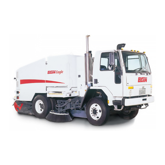
Elgin Eagle Sweeper
History of Sweeping/Principles of Operation Why Sweep
History of Sweeping
Eagle
Mechanical/Broom Sweepers
Water Spray
Brooms
Conveyor
Air Bag Suspension
Hopper
Controls
General Data
Notice
Design Lift Capacity
Maximum Dump Height
Eagle Side View
Eagle SE Rear View
Maximum Dump Height (Bottom of Discharge Door)
Instruments and Controls
Operating Checklist
Starting the Unit
Cold Weather Starting
Transport
Sweeping
Sweeping Patterns
Reversing the Conveyor
Dumping the Hopper
At End of Shift
Stopping the Sweeper
Maintenance
Scheduled Maintenance
Daily Service Checklist
Periodic Service Checklist
After 150 Hours
After 500 Hours
After 1000 Hours
Daily Washdown
Service Procedures
Towing
Auxiliary Engine
Air Pre-Cleaner
Air Cleaner
Auxiliary Engine Fluids
Fuel System
Draining the Fuel Water Separator
Changing Fuel Filter
Bleeding the Fuel System
Hydraulic System
Spray Water System
Notice
Elgin Sweeper Company Recommends Texaco Rando HDZ 68 or Equivalent Hydraulic Oil
Sweeping Patterns
Side Broom Adjustment
Side-To-Side Angle
Front-To-Back Angle
Down Pressure
Main Broom Adjustment
Dirt Shoe Adjustment
Dirt Deflector
Conveyor
Daily Washdown
Winter Storage
Spring Start-Up
Advertisement
Quick Links
1
Controls
2
Instruments and Controls
Download this manual
E a g l e ® E a n d F
OPERATORS MANUAL
Table of
Contents
Previous
Page
Next
Page
1
2
3
4
5
Advertisement
Chapters
Table of Contents
9
Notice
36
Table of Contents
Need help?
Do you have a question about the Eagle E Series and is the answer not in the manual?
Ask a question
Questions and answers
Related Manuals for Elgin Eagle E Series
Floor Machine Elgin Eagle F Series Operator's Manual
(104 pages)
This manual is also suitable for:
Eagle f series
Table of Contents
Save PDF
Print
Rename the bookmark
Delete bookmark?
Delete from my manuals?
Login
Sign In
OR
Sign in with Facebook
Sign in with Google
Upload manual
Upload from disk
Upload from URL


Need help?
Do you have a question about the Eagle E Series and is the answer not in the manual?
Questions and answers