Table of Contents
Advertisement
Quick Links
Valco Instruments Co. Inc.
North America, South America, and Australia/Oceania contact:
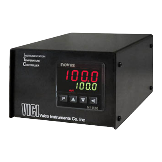
Instrumentation
Temperature Controller
Instruction Manual
Model ITC2
Valco Instruments Co. Inc.
800 · 367· 8424
sales
713 · 688· 9345
tech
713 · 688· 8106
fax
valco@vici.com
Europe, Asia, and Africa contact::
VICI AG International
Schenkon, Switzerland
Int + 41 · 41 · 925· 6200
Int + 41 · 41 · 925· 6201
info@vici.ch
10/20
phone
fax
Advertisement
Table of Contents

Summary of Contents for Valco baby Vici ITC2
- Page 1 Valco Instruments Co. Inc. Instrumentation Temperature Controller Instruction Manual Model ITC2 10/20 North America, South America, and Australia/Oceania contact: Europe, Asia, and Africa contact:: Valco Instruments Co. Inc. VICI AG International 800 · 367· 8424 sales Schenkon, Switzerland 713 · 688· 9345 tech Int + 41 ·...
- Page 2 General Safety Requirements Do not open the controller enclosure. There are no user-serviceable parts inside, and you may cause a dangerous failure. Do not replace the power entry module fuses with anything but 5 x 20 mm 250V 5A FAST BLOW fuses. Do not make physical or electrical contact with the heater assembly controlled by the ITC2 before disconnecting the ITC2 from its power source and allowing adequate time for the heater to cool.
-
Page 3: Table Of Contents
Table of Contents Description ..............................1 Setup and Operation ..........................2 Connections ............................2 Adjusting the Temperature Setpoint ..................2 Verifying Thermocouple Polarity Running Autotune ..........................Initiating the Autotune Sequence: Fast Mode ............2 Initiating the Autotune Sequence: Full Mode ............3 When to Repeat Autotune ...................... - Page 4 This page intentionally left blank for printing purposes...
-
Page 5: Description
Description The ITC2 is designed to control an isothermal zone, such as a Valco heated valve enclosure (HVE), to a high degree of accuracy and stability through the use of a type K thermocou- ple. The thermocouple was chosen because of its low mass, simplicity, and quick response to temperature changes. -
Page 6: Setup And Operation
Setup and Operation Connections 1. Connect the thermocouple and heater power cord to the ITC2 rear panel. NOTE: Take care to verify the polarity of the thermocouple input, as described below. 2. Plug the power cord into the ITC2 and into a properly grounded outlet 3. -
Page 7: Initiating The Autotune Sequence: Full Mode
Initiating the Autotune Sequence: Full Mode 1. Press hold the P key for five seconds. “ Atun ” will appear in the upper red LED and “ oFF ” will appear in the lower green LED 2. Momentarily press the down arrow. When “ FASt ” appears in the lower green LED, press the down arrow again to show “... -
Page 8: Specifications
Specifications Power supply 100 to 240 VAC (±10%), 50/60Hz Maximum consumption 5 amps Environmental conditions Operation temperature 0 - 50°C Relative humidity 80% @ 30°C* Input Input type Type K thermocouple Internal resolution 32767 (15 bits) Resolution of display 0.1 Celsius Control Range -20 to 400 Celsius Rate of reading... -
Page 9: Appendix A: Operation Terms And Principles
Appendix A: Operation Terms and Principles P (band) Pb “P” (band) is the proportion term – the primary term for controlling the error, or deviation from the temperature set point. This setting directly scales the error, so with a small “P” the controller will make small attempts to minimize the error, and with a large “P”... -
Page 10: Warranty
Warranty This Limited Warranty gives the Buyer specific legal rights, and a Buyer may also have other rights that vary from state to state. For a period of 365 calendar days from the date of shipment, Valco Instruments Company, Inc. (hereinafter Seller) warrants the goods to be free from defect in material and workmanship to the original purchaser.
Need help?
Do you have a question about the Vici ITC2 and is the answer not in the manual?
Questions and answers