
Summary of Contents for VIPA IM 053-1CA00
- Page 1 VIPA System SLIO IM | 053-1CA00 | Manual HB300E_IM | RE_053-1CA00 | Rev. 11/29 July 2011...
- Page 2 Copyright © VIPA GmbH. All Rights Reserved. This document contains proprietary information of VIPA and is not to be disclosed or used except in accordance with applicable agreements. This material is protected by the copyright laws. It may not be reproduced, distributed, or altered in any fashion by any entity (either internal or external to VIPA), except in accordance with applicable agreements, contracts or licensing, without the express written consent of VIPA and the business management owner of the material.
-
Page 3: Table Of Contents
Manual VIPA System SLIO Contents Contents About this manual ..................1 Safety information ..................2 Chapter 1 Basics and Assembly ............. 1-1 Safety Information for Users..............1-2 System conception ................1-3 Dimensions ..................1-6 Installation .................... 1-7 Demounting and module exchange ............ 1-10 Wiring.................... - Page 4 Manual VIPA System SLIO Contents HB300E - IM - RE_053-1CA00 - Rev. 11/29...
-
Page 5: About This Manual
Overview Chapter 1: Basics and Assembly The focus of this chapter is on the introduction of the VIPA System SLIO. Here you will find the information required to assemble and wire a controller system consisting of System SLIO components. Besides the dimensions the general technical data of System SLIO will be found. - Page 6 Manual VIPA System SLIO About this manual This manual describes the IM 053-1CA00 of the System SLIO from VIPA. It Objective and contains a description of the structure, project engineering and contents deployment. This manual is part of the documentation package...
-
Page 7: Safety Information
Manual VIPA System SLIO Safety information Safety information The System SLIO is constructed and produced for: Applications conforming with • communication and process control specifications • general control and automation applications • industrial applications • operation within the environmental conditions specified in the technical data •... - Page 8 Manual VIPA System SLIO Safety information HB300E - IM - RE_053-1CA00 - Rev. 11/29...
-
Page 9: Chapter 1 Basics And Assembly
Chapter 1 Basics and Assembly Chapter 1 Basics and Assembly The focus of this chapter is on the introduction of the VIPA System SLIO. Overview Here you will find the information required to assemble and wire a controller system consisting of System SLIO components. -
Page 10: Safety Information For Users
Manual VIPA System SLIO Chapter 1 Basics and Assembly Safety Information for Users VIPA modules make use of highly integrated components in MOS- Handling of Technology. These components are extremely sensitive to over-voltages electrostatic that can occur during electrostatic discharges. -
Page 11: System Conception
Manual VIPA System SLIO Chapter 1 Basics and Assembly System conception System SLIO is a modular automation system for assembly on a 35mm Overview mounting rail. By means of the peripheral modules with 2, 4 or 8 channels this system may properly be adapted matching to your automation tasks. - Page 12 Manual VIPA System SLIO Chapter 1 Basics and Assembly Each periphery module consists of a terminal and an electronic module. Periphery modules Terminal module Electronic module Terminal module The terminal module serves to carry the electronic module, contains the backplane bus with power supply for the electronic, the DC 24V power section supply and the staircase-shaped terminal for wiring.
- Page 13 Manual VIPA System SLIO Chapter 1 Basics and Assembly Accessories Shield bus carrier The shield bus carrier serves to carry the shield bus (10mm x 3mm) to connect cable shields. Shield bus carriers, shield bus and shield fixings are not in the scope of delivery.
-
Page 14: Dimensions
Manual VIPA System SLIO Chapter 1 Basics and Assembly Dimensions Dimensions bus coupler 76.5 48.5 Dimensions periphery module 76.5 12.9 Dimensions electronic module 12.9 Dimensions in mm HB300E - IM - RE_053-1CA00 - Rev. 11/29... -
Page 15: Installation
Manual VIPA System SLIO Chapter 1 Basics and Assembly Installation There is a locking lever at the top side of the terminal module. For Functional mounting and demounting this locking lever is to be turned upwards until principle this engages audible. - Page 16 Manual VIPA System SLIO Chapter 1 Basics and Assembly The modules were directly be mounted to the mounting rail and so Mounting connected to the backplane bus and the power supply for the electronic Proceeding and power section. Up to 64 modules may be mounted. Please consider here that the sum current of the electronic power supply does not exceed the maximum value of 3A.
- Page 17 Manual VIPA System SLIO Chapter 1 Basics and Assembly • Mounting Mount the periphery modules you want. periphery modules Clack • After mounting the whole system, to protect the backplane bus Mounting the bus cover connectors at the last module you have to mount the bus cover, now.
-
Page 18: Demounting And Module Exchange
Manual VIPA System SLIO Chapter 1 Basics and Assembly Demounting and module exchange With demounting and exchange of a module, head module (e.g. bus Proceeding coupler) or a group of modules for mounting reasons you have always to remove the electronic module of the just mounted right module. After the mounting it may be plugged again. - Page 19 Manual VIPA System SLIO Chapter 1 Basics and Assembly • For mounting turn the locking lever of the module to be mounted upwards. • To mount the module put it to the gap between the both modules and push it, guided by the stripes at both sides, to the mounting rail.
- Page 20 Manual VIPA System SLIO Chapter 1 Basics and Assembly • For mounting turn all the locking lever of the head module to be mounted upwards. • To mount the head module put it to the left module and push it, guided by the stripes, to the mounting rail.
- Page 21 Manual VIPA System SLIO Chapter 1 Basics and Assembly • Pull the module group forward. • For mounting turn all the locking lever of the module group to be mounted upwards. • To mount the module group put it to the gap between the both modules and push it, guided by the stripes at both sides, to the mounting rail.
-
Page 22: Wiring
Manual VIPA System SLIO Chapter 1 Basics and Assembly Wiring Terminals with spring clamp technology are used for wiring. The spring Connectors clamp technology allows quick and easy connection of your signal and supply lines. In contrast to screw terminal connections this type of connection is vibration proof. - Page 23 Manual VIPA System SLIO Chapter 1 Basics and Assembly Standard wiring SysDC5V max. 3A DC24V max. 10A DC24V DC24V (1) DC 24V for power section supply I/O area (max 10A) (2) DC 24V for electronic power supply bus coupler and I/O area...
- Page 24 If the 10A for the power section supply is no longer sufficient, you may use Deployment of the the power module from VIPA with the order number 007-1AB00. So you power modules have also the possibility to define isolated groups.
- Page 25 Manual VIPA System SLIO Chapter 1 Basics and Assembly To attach the shield the mounting of shield bus carriers are necessary. Shield attachment The shield bus carrier (available as accessory) serves to carry the shield bus to connect cable shields.
-
Page 26: Trouble Shooting - Leds
Manual VIPA System SLIO Chapter 1 Basics and Assembly Trouble shooting - LEDs Each module has the LEDs RUN and MF on its front side. Errors or General incorrect modules may be located by means of these LEDs. In the following illustrations flashing LEDs are marked by ☼. -
Page 27: Installation Guidelines
Manual VIPA System SLIO Chapter 1 Basics and Assembly Installation guidelines The installation guidelines contain information about the interference free General deployment of System SLIO. There is the description of the ways, interference may occur in your control, how you can make sure the electromagnetic digestibility (EMC), and how you manage the isolation. - Page 28 Manual VIPA System SLIO Chapter 1 Basics and Assembly In the most times it is enough to take care of some elementary rules to Basic rules for guarantee the EMC. Please regard the following basic rules when installing your PLC.
- Page 29 Manual VIPA System SLIO Chapter 1 Basics and Assembly Electrical, magnetically and electromagnetic interference fields are Isolation of weakened by means of an isolation, one talks of absorption. conductors Via the isolation rail, that is connected conductive with the rack, interference currents are shunt via cable isolation to the ground.
-
Page 30: General Data
Manual VIPA System SLIO Chapter 1 Basics and Assembly General data Conformity and approval Conformity 2006/95/EG Low-voltage directive Approval UL 508 Approval for USA and Canada others RoHs Product is unleaded Protection of persons and device protection Type of protection... -
Page 31: Chapter 2 Hardware Description
Manual VIPA System SLIO Chapter 2 Hardware description Chapter 2 Hardware description Here the hardware components of the IM 053-1CA00 are more described. Overview You will find the technical data at the end of this chapter. Content Topic Page Chapter 2 Hardware description ............. -
Page 32: Properties
Manual VIPA System SLIO Chapter 2 Hardware description Properties • 16 Rx and 16 Tx PDOs Features • 2 SDOs • Support of every transfer rates • PDO linking • PDO mapping: variable • CAN bus address setting via DIP switch. -
Page 33: Structure
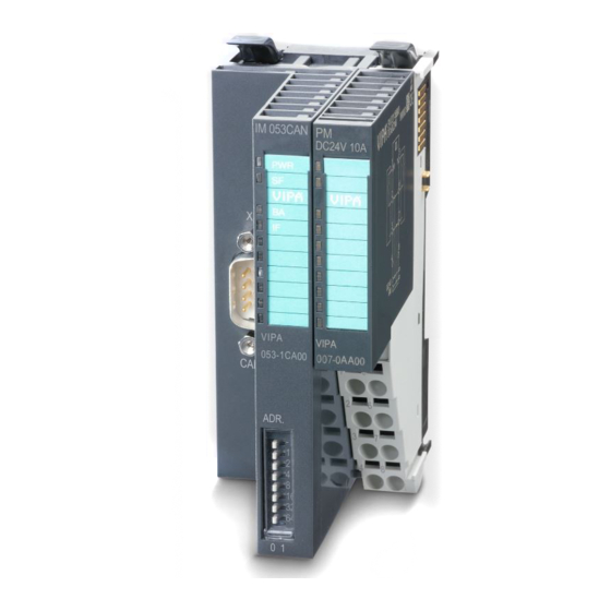
Manual VIPA System SLIO Chapter 2 Hardware description Structure Locking lever terminal module 053-1CA00 Labeling strip bus interface LED status indication bus interface Labeling strip power module LED status indication power module Backplane bus DC 24V power section supply Power module... - Page 34 Manual VIPA System SLIO Chapter 2 Hardware description For wires with a core cross-section of 0.08mm up to 1.5mm Terminal DC24V DC24V DC24V Pos. Function Type Description not connected DC 24V DC 24V for power section supply GND for power section supply...
- Page 35 Manual VIPA System SLIO Chapter 2 Hardware description Connecting the bus The CAN bus communication medium is a screened three-core cable. All stations on systems having more than two stations are wired in parallel. This means that the bus cable must be looped from station to station without interruptions.
-
Page 36: Technical Data
Manual VIPA System SLIO Chapter 2 Hardware description Technical Data Order number 053-1CA00 Type IM 053CAN Module ID Technical data power supply Power supply (rated value) DC 24 V Power supply (permitted range) DC 20.4...28.8 V Reverse polarity protection Current consumption (no-load operation) -
Page 37: Chapter 3 Deployment
Manual VIPA System SLIO Chapter 3 Deployment Chapter 3 Deployment This chapter contains the description of the IM 053-1CA00 with CANopen. Overview Besides the fast introduction concerning the project engineering for "experts" you may find an introduction to the telegram structure and the function codes of CANopen. -
Page 38: Basics Can
SDOs provide access to the object directory for read and write operations For every CANopen slave from VIPA there is a EDS file available. This file EDS file may either be found on the supplied storage media or at the download area of www.vipa.de. - Page 39 Ω terminated by a 120 terminating resistor. Your VIPA CAN bus coupler contains a 9pin socket. You must use this socket to connect the CAN bus coupler as a slave directly to your CAN bus network. All devices on the network use the same transfer rate.
-
Page 40: Fast Introduction
Chapter 3 Deployment Manual VIPA System SLIO Fast introduction Overview This section is for experienced CANopen user that are already common with CAN. It will be shortly outlined, which messages are necessary for the deployment of the System SLIO with CAN in the start configuration. - Page 41 Manual VIPA System SLIO Chapter 3 Deployment Digital in-/outputs The CAN messages with digital input data are represented as follows: Identifier 0x180+Node address + up to 8byte user data Identifier 11bit DI 0 8bit DI 1 8bit DI 2 8bit...
- Page 42 Chapter 3 Deployment Manual VIPA System SLIO Node Guarding For the System SLIO works per default in event-controlled mode (no cyclic DataExchange), a node failure is not always immediately detected. Remedy is the control of the nodes per cyclic state request (Node Guarding).
- Page 43 Manual VIPA System SLIO Chapter 3 Deployment Emergency Object To send internal device failures to other participants at the CAN bus with a high priority, the SLIO CAN bus coupler supports the Emergency Object. To activate the emergency telegram, you need the COB-Identifier that is fixed after boot-up in the object directory of the variable 0x1014in hexadecimal view: 0x80 + Module-ID.
-
Page 44: Accessing The System Slio
EDS file To configure the slave connections in your own configuration tool, you’ve got all the information about your VIPA-modules in form of an electronic data sheet file. Install this EDS file in you configuration tool. The current EDS file may be found in the download area of www.vipa.de. - Page 45 Manual VIPA System SLIO Chapter 3 Deployment Mapping sequence 1. Digital modules of the module 2. Analog modules classes 3. CPs 4. Function modules: counter 5. Function modules: SSI 6. Function modules: PWM 7. Function modules: ETS (per default with each module 6 ETS entries are mapped)
- Page 46 Chapter 3 Deployment Manual VIPA System SLIO Access via SDO The object directory may be r/w accessed via SDO (service data object). Here data of any length may be transferred. If necessary the data were distributed several messages with same identifier (segmentation).
- Page 47 Manual VIPA System SLIO Chapter 3 Deployment The modules are parameterized by SDO transfer. Here a parameterizable Accessing module is addressed by subindex at the system bus. parameter data The parameters may be accessed by indices. Information concerning the index allocation may be found in the description of the corresponding System SLIO module.
- Page 48 Chapter 3 Deployment Manual VIPA System SLIO Process and diagnostic interrupt data of System SLIO modules with Accessing interrupt capability were automatically sent by an emergency telegram if diagnostics data the interrupt is activated by parameterization. There is the possibility to request diagnostics data via SDO.
-
Page 49: Transfer Rate And Module-Id
Manual VIPA System SLIO Chapter 3 Deployment Transfer rate and module-ID There is the possibility to specify transfer rate and module-ID by means of Overview the address selector. The settings are permanently stored in an EEPROM and may any time be changed. - Page 50 Chapter 3 Deployment Manual VIPA System SLIO Programming For a further period of 10s, as long as the LEDs SF and BA are blinking, module-ID you may set the module-ID in a range of 1 ... 125 by means of the address selector.
-
Page 51: Telegram Structure
Manual VIPA System SLIO Chapter 3 Deployment Telegram structure The CANopen telegrams have the following structure according to Identifier CiA DS-301: Identifier Byte Bit 7 ... Bit 0 Bit 3 ... Bit 0: most significant 4 bits of the module-ID Bit 7 ... -
Page 52: Pdo
Chapter 3 Deployment Manual VIPA System SLIO CANopen Every object is associated with a function code. You can obtain the required function code from the following table: function codes Object Function code Receiver Definition Function (4 bits) 0000 Broadcast CiA301... - Page 53 Manual VIPA System SLIO Chapter 3 Deployment In many fieldbus systems the whole process image is transferred - mostly more or less cyclically. CANopen is not limited to this communication principle, for CAN supports more possibilities through multi master bus access coordination.
- Page 54 Chapter 3 Deployment Manual VIPA System SLIO Mapping sequence 1. Digital modules of the module 2. Analog modules classes 3. CPs 4. Function modules: counter 5. Function modules: SSI 6. Function modules: PWM 7. Function modules: ETS (per default with each module 6 ETS entries are mapped)
- Page 55 Manual VIPA System SLIO Chapter 3 Deployment PDO identifier The most important communication parameter of a PDOs is the CAN identifier (also called "Communication Object Identifier", COB-ID). It COB-ID serves the identification of the data and sets the priority of bus access.
- Page 56 Chapter 3 Deployment Manual VIPA System SLIO PDO linking If the Consumer-Producer model of the CANopen PDOs shall be used for direct data transfer between nodes (without master), you have to adjust the identifier distribution accordingly, so that the TxPDO identifier of the producer is identical with the RxPDO identifier of the consumer: This procedure is called PDO linking.
- Page 57 Manual VIPA System SLIO Chapter 3 Deployment The parameter "PDO transmission type" fixes how the sending of the PDO transmission PDOs is initialized and what to do with received ones: type Transmission Type Cyclical Acyclical Synchronous Asynchronous 1-240 254, 255...
- Page 58 Chapter 3 Deployment Manual VIPA System SLIO The Service Data Object (SDO) serves the read or write access to the object directory. The CAL layer 7 protocol gives you the specification of the Multiplexed-Domain-Transfer-Protocol that is used by the SDOs. This...
- Page 59 Manual VIPA System SLIO Chapter 3 Deployment SDO error codes Code Error 0x05030000 Toggle bit not alternated 0x05040000 SDO protocol timed out 0x05040001 Client/server command specifier not valid or unknown 0x05040002 Invalid block size (block mode only) 0x05040003 Invalid sequence number (block mode only)
- Page 60 Chapter 3 Deployment Manual VIPA System SLIO Object directory The CANopen object directory contains all relevant CANopen objects for Structure the bus coupler. Every entry in the object directory is marked by a 16bit index. If an object exists of several components (e.g. object type Array or Record), the components are marked via an 8bit sub-index.
- Page 61 Manual VIPA System SLIO Chapter 3 Deployment Index Content of Object Object directory 0x1000 Device type overview 0x1001 Error register 0x1003 Error store 0x1004 Number of PDOs 0x1005 SYNC identifier 0x1006 SYNC interval 0x1007 Synchronous Window Length 0x1008 Device name...
- Page 62 Chapter 3 Deployment Manual VIPA System SLIO Index Content of Object 0x5400 Counter Module: count value 0x5401 Counter Module: latch value 0x5402 Counter Module: status value 0x5403 Counter Module: µsTicker 0x5410 SSI Module: SSI value 0x5411 SSI Module: µsTicker 0x5420...
- Page 63 Manual VIPA System SLIO Chapter 3 Deployment Device Type Index Sub- Name Type Attr. Map. Default value Meaning index 0x1000 0 Device Unsigned32 ro 0x00050191 Statement of device type Type The 32bit value is divided into two 16bit fields: Additional information device...
- Page 64 Chapter 3 Deployment Manual VIPA System SLIO Error store Index Sub- Name Type Attr. Map. Default value Meaning index 0x1003 0 Predefined Unsigned8 0x00 Object 0x1003 contains a error field description of the error that (error store) has occurred in the device -...
- Page 65 Device name of the bus device name string coupler VIPA IM 053 1CA00 = VIPA CANopen slave IM 053-1CA00 Since the returned value is longer than 4byte, the segmented SDO protocol is used for transmission. HB300E - IM - RE_053-1CA00 - Rev. 11/29...
- Page 66 0x1009 0 Manufacturer Visible Hardware version number of Hardware string bus coupler version VIPA IM 053 1CA00 = 1.00 Since the returned value is longer than 4byte, the segmented SDO protocol is used for transmission. Software version Index Sub- Name Type Attr.
- Page 67 Manual VIPA System SLIO Chapter 3 Deployment Life time factor Index Sub- Name Type Attr. Map. Default value Meaning index 0x100D 0 Life time factor Unsigned8 0x00 Life time factor x guard time = life time (watchdog for life guarding) If a guarding telegram is not received within the life time, the node enters the error state.
- Page 68 Chapter 3 Deployment Manual VIPA System SLIO Load default values Index Sub- Name Type Attr. Map. Default value Meaning index 0x1011 0 Restore Unsigned8 0x01 Number of reset options parameters Restore all Unsigned32 rw 0x01 Resets all parameters parameters to their default values By writing the string "load"...
- Page 69 Manual VIPA System SLIO Chapter 3 Deployment Producer heartbeat time Index Sub- Name Type Attr. Map. Default value Meaning index 0x1017 0 Producer Unsigned16 rw 0x0000 Defines the cycle time of heartbeat time heartbeat in ms Identity Object Index Sub-...
- Page 70 Chapter 3 Deployment Manual VIPA System SLIO Error Behavior Index Sub- Name Type Attr. Map. Default value Meaning index 0x1029 0 Error behavior Unsigned8 0x02 Number of Error Classes Communication Unsigned8 0x00 Communication Error Error Manufacturer Unsigned8 0x00 Manufacturer specific error specific error As soon as a device failure is detected in "operational"...
- Page 71 Manual VIPA System SLIO Chapter 3 Deployment Communication parameter RxPDO2 Index Sub- Name Type Attr. Map. Default value Meaning index 0x1401 0 Number of Unsigned8 0x02 Communication parameter for the first receive PDOs, sub- Elements index 0: number of following...
- Page 72 Chapter 3 Deployment Manual VIPA System SLIO Communication parameter RxPDO5 Index Sub- Name Type Attr. Map. Default value Meaning index 0x1404 0 Number of Unsigned8 0x02 Communication parameter for the first receive PDOs, sub- Elements index 0: number of following...
- Page 73 Manual VIPA System SLIO Chapter 3 Deployment Communication parameter RxPDO8 Index Sub- Name Type Attr. Map. Default value Meaning index 0x1407 0 Number of Unsigned8 0x02 Communication parameter for the first receive PDOs, sub- Elements index 0: number of following...
- Page 74 Chapter 3 Deployment Manual VIPA System SLIO Communication parameter RxPDO11 Index Sub- Name Type Attr. Map. Default value Meaning index 0x140A 0 Number of Unsigned8 0x02 Communication parameter for the first receive PDOs, sub- Elements index 0: number of following...
- Page 75 Manual VIPA System SLIO Chapter 3 Deployment Communication parameter RxPDO14 Index Sub- Name Type Attr. Map. Default value Meaning index 0x140D 0 Number of Unsigned8 0x02 Communication parameter for the first receive PDOs, sub- Elements index 0: number of following...
- Page 76 Chapter 3 Deployment Manual VIPA System SLIO Mapping RxPDO1 Index Sub- Name Type Attr. Map. Default value Meaning index 0x1600 0 Number of Unsigned8 0x01 Mapping parameter of the first Elements receive PDO; sub-index 0: number of mapped objects 1. mapped...
- Page 77 Manual VIPA System SLIO Chapter 3 Deployment Mapping RxPDO3- RxPDO16 Index Sub- Name Type Attr. Map. Default value Meaning index 0x1602 Number of Unsigned8 0x01 Mapping parameter of the 3. Elements to 10. receive PDO; sub-index 0x160F 0: number of mapped objects 1.
- Page 78 Chapter 3 Deployment Manual VIPA System SLIO Communication parameter TxPDO2 Index Sub- Name Type Attr. Map. Default value Meaning index 0x1801 0 Number of Unsigned8 0x05 Communication parameter of Elements the second transmit PDO, sub-index 0: number of following parameters...
- Page 79 Manual VIPA System SLIO Chapter 3 Deployment Communication parameter TxPDO5 Index Sub- Name Type Attr. Map. Default value Meaning index Communication parameter for 0x1804 0 Number of Unsigned8 0x05 the 5. transmit PDO. Elements COB-ID Unsigned32 rw 0x80000000 COB-ID TxPDO5...
- Page 80 Chapter 3 Deployment Manual VIPA System SLIO Communication parameter TxPDO8 Index Sub- Name Type Attr. Map. Default value Meaning index 0x1807 0 Number of Unsigned8 0x05 Communication parameter for Elements the 8. transmit PDO. COB-ID Unsigned32 rw 0x80000000 COB-ID TxPDO8...
- Page 81 Manual VIPA System SLIO Chapter 3 Deployment Communication parameter TxPDO11 Index Sub- Name Type Attr. Map. Default value Meaning index 0x180A 0 Number of Unsigned8 0x05 Communication parameter for Elements the 11. transmit PDO. COB-ID Unsigned32 rw 0x80000000 COB-ID TxPDO11...
- Page 82 Chapter 3 Deployment Manual VIPA System SLIO Communication parameter TxPDO14 Index Sub- Name Type Attr. Map. Default value Meaning index 0x180D 0 Number of Unsigned8 0x05 Communication parameter for Elements the 14. transmit PDO. COB-ID Unsigned32 rw 0x80000000 COB-ID TxPDO14...
- Page 83 Manual VIPA System SLIO Chapter 3 Deployment Mapping TxPDO1 Index Sub- Name Type Attr. Map. Default value Meaning index 0x1A00 0 Number of Unsigned8 depending on Mapping parameter of the first Elements transmit PDO; sub-index 0: components number of mapped objects fitted 1.
- Page 84 Chapter 3 Deployment Manual VIPA System SLIO Mapping TxPDO3- TxPDO16 Index Sub- Name Type Attr. Map. Default value Meaning index 0x1A02 Number of Unsigned8 depending on Mapping parameter of the 3. Elements to 10 th transmit PDO; sub- 0x1A0F components...
- Page 85 0x200A 0 Software Visible Software package version package string version VIPA IM 053 1CA00 = 1.0.2 Since the returned value is longer than 4byte, the segmented SDO protocol is used for transmission. SLIO bus version Index Sub- Name Type Attr.
- Page 86 Chapter 3 Deployment Manual VIPA System SLIO Module hardware revision Index Sub- Name Type Attr. Map. Default value Meaning index 0x2029 0 Number of Unsigned8 Contains general information connected about the device modules (number of entries) Module 1 Visible Hardware revision of...
- Page 87 Manual VIPA System SLIO Chapter 3 Deployment CAN coupler FPGA version Index Sub- Name Type Attr. Map. Default value Meaning index 0x2030 0 FPGA version Unsigned16 ro FPGA Version Module FPGA version Index Sub- Name Type Attr. Map. Default value Meaning...
- Page 88 Chapter 3 Deployment Manual VIPA System SLIO CAN coupler Product version Index Sub- Name Type Attr. Map. Default value Meaning index 0x2050 0 FPGA version Visible Product Version string VIPA 053-1CA00 = 01.V10.001 The segmented SDO protocol is used for transmission.
- Page 89 Manual VIPA System SLIO Chapter 3 Deployment Module Diagnostic data record 0 Index Sub- Name Type Attr. Map. Default value Meaning index 0x2F00 0 Number of Unsigned8 Contains general information connected about the device modules (number of entries) Module 1...
- Page 90 Chapter 3 Deployment Manual VIPA System SLIO 1. Module Parameter Index Sub- Name Type Attr. Map. Default value Meaning index 0x3100 0 Number of Unsigned8 depending on Number of configurable the number modules Elements 0x00 : no module available configurable...
- Page 91 Manual VIPA System SLIO Chapter 3 Deployment 2..65. Module Parameter Index Sub- Name Type Attr. Map. Default value Meaning index 0x3101 1 2. Prm Unsigned8 depending on 2. Parameter byte of the 1. Module 1. configurable module the compo- nents fitted 2.
- Page 92 Chapter 3 Deployment Manual VIPA System SLIO Write Parameters Index Sub- Name Type Attr. Map. Default value Meaning index 0x31FF 0 Number of Unsigned8 depending on Number of configurable Elements the number modules 0x00 : no module available configurable 0xXX : XX number of...
- Page 93 Manual VIPA System SLIO Chapter 3 Deployment Access to record set bus coupler Index Sub- Name Type Attr. Map. Default value Meaning index 0x3200 0x00 Number of Unsigned8 0xFF Number of record sets Elements 0x50 Device name Visible Device name...
- Page 94 Chapter 3 Deployment Manual VIPA System SLIO 2/4bit Digital inputs Index Sub- Name Type Attr. Map. Default value Meaning Index 0x5000 0x00 2/4bit digital Unsigned8 0x01 Number of available digital input block 8bit input blocks 0x01 1. input block Unsigned8 1.
- Page 95 Manual VIPA System SLIO Chapter 3 Deployment 2/4bit Change Polarity Digital outputs Index Sub- Name Type Attr. Map. Default value Meaning Index 0x5202 0x00 2/4bit digital Unsigned8 Depending Number of available digital ouput block on the com- 8bit output blocks...
- Page 96 Chapter 3 Deployment Manual VIPA System SLIO Counter value Index Sub- Name Type Attr. Map. Default value Meaning Index 0x5400 0x00 Number of Unsigned8 depending on Number of available counter max. entries the compo- values nents fitted 0x01 1. counter Unsigned32 ro 1.
- Page 97 Manual VIPA System SLIO Chapter 3 Deployment SSI value Index Sub- Name Type Attr. Map. Default value Meaning Index 0x5410 0x00 Number of Unsigned8 depending on Number of available max. entries the compo- SSI values nents fitted 0x01 1. SSI value Unsigned32 ro 1.
- Page 98 Chapter 3 Deployment Manual VIPA System SLIO µs ticker time Index Sub- Name Type Attr. Map. Default value Meaning index 0x5431 0 µs ticker Unsigned32 ro 0x0000 Time of the 32bit System [ms] SLIO µs ticker. Status ETS Digital outputs...
- Page 99 Manual VIPA System SLIO Chapter 3 Deployment Counter control value Index Sub- Name Type Attr. Map. Default value Meaning Index 0x5602 0x00 Number of Unsigned8 depending on Number of available counter max. entries the compo- control values nents fitted 0x01 1.
- Page 100 Chapter 3 Deployment Manual VIPA System SLIO 8bit digital inputs Index Sub- Name Type Attr. Map. Default value Meaning Index 0x6000 0x00 8bit digital Unsigned8 0x01 Number of available digital input block 8bit input blocks 0x01 1. input block Unsigned8 1.
- Page 101 Manual VIPA System SLIO Chapter 3 Deployment 8bit change polarity digital outputs Index Sub- Name Type Attr. Map. Default value Meaning Index 0x6202 0x00 8bit digital Unsigned8 Depending Number of available digital output block on the com- 8bit output blocks...
- Page 102 Chapter 3 Deployment Manual VIPA System SLIO 8bit error value digital outputs Index Sub- Name Type Attr. Map. Default value Meaning Index 0x6207 0x00 8bit digital Unsigned8 Depending Number of available digital output block on the 8bit output blocks components...
- Page 103 Manual VIPA System SLIO Chapter 3 Deployment Analog input interrupt trigger selection Index Sub- Name Type Attr. Map. Default value Meaning Index 0x6421 0x00 Number of Unsigned8 depending on Number of available analog Inputs the compo- inputs nents fitted 0x01 Trigger 1.
- Page 104 Chapter 3 Deployment Manual VIPA System SLIO Event driven analog inputs Index Sub- Name Type Attr. Map. Default value Meaning index 0x6423 0x00 Global interrupt Boolean FALSE ("0") Activates the event-driven enable transmission of PDOs with analog inputs Although the analog inputs are -acc. to CANopen - per default set to the transmission type 255 (event triggered) in the TxPDO2, the "event"...
- Page 105 Manual VIPA System SLIO Chapter 3 Deployment Lower limit value analog inputs Index Sub- Name Type Attr. Map. Default value Meaning Index 0x6425 0x00 Number of Unsigned8 depending on Number of available analog Inputs the compo- inputs nents fitted 0x01 Lower limit 1.
- Page 106 Chapter 3 Deployment Manual VIPA System SLIO Analog output error mode Index Sub- Name Type Attr. Map. Default value Meaning Index 0x6443 0x00 Analog output Unsigned8 Depending Number of available analog block on the com- outputs ponents fitted 0x01 1. analog...
- Page 107 Manual VIPA System SLIO Chapter 3 Deployment 0x05030000 //Toggle bit not alternated SDO Abort Codes 0x05040000 //SDO protocol timed out 0x05040001 //Client/server command specify not valid or unknown 0x05040002 //Invalid block size (block mode only) 0x05040003 //Invalid sequence number (block mode only)
- Page 108 Chapter 3 Deployment Manual VIPA System SLIO Emergency Object The SLIO CAN bus coupler is provided with the emergency object to notify Overview other devices connected to the CANopen bus about internal error events or CAN-Bus errors. It has a high priority and gives you important information about the states of device and network.
- Page 109 Manual VIPA System SLIO Chapter 3 Deployment Network management Network management (NMT) provides the global services specifications for Übersicht network supervision and management. This includes the login and logout of the different network devices, the supervision of these devices as well as the processing of exceptions.
- Page 110 (0x100D) has been set to zero by an SDO download from the master, the expiry of the guard time is not monitored and the module remains in its current operating mode. The VIPA CAN coupler also supports the Heartbeat Mode in addition to Heartbeat Node Guarding.
Need help?
Do you have a question about the IM 053-1CA00 and is the answer not in the manual?
Questions and answers