
Summary of Contents for EqualLogic FS7500
- Page 1 EqualLogic FS7500 Controller Hardware Maintenance PS Series Firmware Version 5.1 EqualLogic FS7500...
- Page 2 Copyright 2011 Dell, Inc. All rights reserved. Dell is a trademark of Dell, Inc. EqualLogic is a registered trademark. All trademarks and registered trademarks mentioned herein are the property of their respective owners. Information in this document is subject to change without notice.
-
Page 3: Table Of Contents
1 Basic Controller Information .......................1-1 FS7500 Controller Components .........................1-1 FS7500 Controller Front Panel........................1-2 LCD Screen and Control Keys......................1-2 Drive Status Indicator LEDs ........................1-3 FS7500 Controller Back Panel ........................1-4 Network Status LEDs...........................1-6 2 Installing System Components ......................2-1 Safety Recommendations ...........................2-1 Recommended Tools ..........................2-1 Required Hardware That Is Not Supplied ....................2-2... - Page 4 EqualLogic FS7500 Controller Hardware Maintenance Table of Contents Installing the Replacement Controller ....................3-2 Attaching the Cables ..........................3-2 Turning on the Power...........................3-2 Obtaining the Service Tag........................3-2 Attach the Controller to the NAS Node Pair..................3-2 Removing and Installing a Disk Drive .......................3-2 Disk Drive Handling Requirements .....................3-2...
-
Page 5: Preface
This manual describes how to maintain and troubleshoot the customer replaceable components of the EqualLogic FS7500 Controller. With the addition of the EqualLogic FS7500, Dell provides a unified view of both block storage and a high- performance, scalable NAS (Network Attached Storage) service. -
Page 6: Technical Support And Customer Service
Preface EqualLogic FS7500 Controller Hardware Maintenance Technical Support and Customer Service Dell’s support service is available to answer your questions about FS Series systems. If you have an Express Service Code, have it ready when you call. The code helps Dell’s automated-support telephone system direct your call more efficiently. -
Page 7: Basic Controller Information
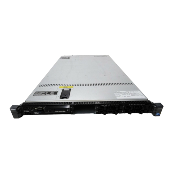
FS7500 Controller Components Figure 1-1 shows the FS7500 controller components. The only customer replaceable components in the FS7500 are the bezel, the hard drives, and the power supplies. For more information about customer replaceable components, see Chapter 2, Installing System Components. -
Page 8: Fs7500 Controller Front Panel
Hard drives (6) Retaining Screws (under latch) LCD Screen and Control Keys The LCD screen control keys display useful information about the FS7500 Controller, including the service tag. For more information about the service tag, refer to Chapter 4. 1–2... -
Page 9: Drive Status Indicator Leds
LCD panel. Drive Status Indicator LEDs Each hard drive in the FS7500 Controller has two status indicator LEDs. One LED displays whether the hard drive is active (powered on). The other LED displays the current operational state of the drive. Figure 1-4 shows the location of the two LEDs, and Table 1-4 describes their behavior. -
Page 10: Fs7500 Controller Back Panel
Blinks green, amber, then off Drive predicted failure Blinking amber, 4x per second Drive failed Slow blinking green Drive rebuilding Steady green Drive online FS7500 Controller Back Panel Figure 1-5 shows the back panel of the FS7500 Controller. 1–4... - Page 11 EqualLogic FS7500 Controller Hardware Maintenance Basic Controller Information Figure 1-5: FS7500 Controller Back Panel Table 1-6: FS7500 Controller Back Panel Components Number Component Internal network and SAN network connectors Client network connections USB port (to BPS) System power-on status LED...
-
Page 12: Network Status Leds
EqualLogic FS7500 Controller Hardware Maintenance Basic Controller Information Network Status LEDs The internal and SAN network connectors have two LEDs that indicate the status of the network connections. Table 1-7: Network Status LEDs Number Component Network on/off LED. Shows steady green when on. -
Page 13: Installing System Components
You need at least two people to install the hardware. Use proper lifting and carrying techniques when unpacking and moving the components. • Make sure each FS7500 Controller is fully grounded at all times to prevent damage from electrostatic discharge. •... -
Page 14: Required Hardware That Is Not Supplied
See Network Connection Requirements and Recommendations on page 2- Hardware Protection When not installed in a rack, a FS7500 Controller must be in its original packaging or placed on a sturdy surface that is protected from electrostatic discharge. When handling a FS7500 Controller, make sure you use the electrostatic wrist strap that is shipped with the controller or a similar form of protection. -
Page 15: Removing And Reinstalling The Controller Bezel
Removing and Reinstalling the Controller Bezel Removing the Controller Bezel To remove the FS7500 Controller bezel, see Figure 2-2 and follow these steps: 1. Use the key to unlock the bezel, if it is locked. 2. Push up on the release latch on the left side of the bezel and carefully pull out the bezel from the left side of the controller. -
Page 16: Attaching The Controller Bezel
EqualLogic FS7500 Controller Hardware Maintenance Installing System Components Figure 2-2: Removing the Controller Bezel Attaching the Controller Bezel To attach the controller bezel, see Figure 2-3 and follow these steps: 1. Insert the right side of the bezel into the slot on the right side of the controller. (Callout 1) 2. -
Page 17: Bps And Power Connections
Installing System Components BPS and Power Connections Each FS7500 Controller is connected to a different BPS power module and a different source of power. You can then verify that each controller is operational. Figure 2-4 shows the two controllers and the BPS properly connected. -
Page 18: Network Configuration Overview
For security reasons, the internal network is usually a private network and the client network must be separate from the SAN and from the internal network. An FS7500 Controller has three four-port NICs, plus a single network interface port in the lower left corner of the back panel. These ports are dedicated to specific networks: •... -
Page 19: Network Connection Requirements And Recommendations
- eth3: Client Network Connection Requirements and Recommendations At a minimum, you can connect all the network ports in an EqualLogic FS7500 to the same physical switch. However, this configuration is appropriate only for demonstration or testing purposes because the network switch is a single point of failure. Dell recommends that you use a highly-available network switch configuration for the client, SAN, and internal network connections. -
Page 20: Steps For Connecting Network Cables
4. Use the cable management system to organize the network cables. See Managing the Controller Cables on page 2-11. Figure 2-6 shows the recommended EqualLogic FS7500 network configuration. Figure 2-7 shows the minimum network configuration, and Table 2-3 describes the components in that configuration. - Page 21 EqualLogic FS7500 Controller Hardware Maintenance Installing System Components Figure 2-6: EqualLogic FS7500 Network Configuration – Recommended 2–9...
-
Page 22: Connecting San And Internal Network Cables
EqualLogic FS7500 Controller Hardware Maintenance Installing System Components Figure 2-7: EqualLogic FS7500 Network Configuration – Minimum Table 2-3: Minimum Network Configuration Component Descriptions Callout Description Switch stack (used for both client and internal connections) 2, 3 FS7500 Controllers Connecting SAN and Internal Network Cables For the recommended configuration, see Figure 2-6. -
Page 23: Connecting The Client Network Cables
The cable connections are described in Steps for Connecting Network Cables on page 2- • Adding a service loop to the FS7500 controller installed in the provided rails. A service loop is an extra length of cable between the rear of the controller and the rack. The additional cable allows you to slide the controller forward on the rails for servicing without having to disconnect the cables and power cables. -
Page 24: Routing The Power Cables Through The Strain Relief Straps
EqualLogic FS7500 Controller Hardware Maintenance Installing System Components Figure 2-8: Controller Cable Connections Table 2-4: Controller Cable Connections Number Description SAN and internal network connections, including the IPMI cable USB connection to BPS Client network connections Power connection to BPS power module... -
Page 25: Bundling The Network And Power Cables
Securing the Network and Power Cable Bundles to the Rails The FS7500 controller rails have brackets attached to the rear of each rail. These brackets extend beyond the back of the system when the rails are installed. Figure 2-10 shows the location of the hook-and-loop fasteners on the brackets. - Page 26 EqualLogic FS7500 Controller Hardware Maintenance Installing System Components Figure 2-10: Cable Management Brackets Secure the bundled cords to the brackets as follows: 1. Use the hook-and-loop fastener to secure the bundled network cables to the bracket on the rail on your left as you face the back of the controller.
-
Page 27: Steps For Managing Cables Using A Service Loop
EqualLogic FS7500 Controller Hardware Maintenance Installing System Components Figure 2-11: Bundled Signal and Power Cables Figure 2-12 shows the back panel of the FS7500 controller with the bundled cords secured to the rails. Figure 2-12: Securing the Signal and Power Cable Bundles Steps for Managing Cables Using a Service Loop A service loop is an extra length of cable between the rear of the rack and the controller. -
Page 28: Routing The Power Cables Through The Strain Relief Straps
Extending the Controller into Service Position From the front of the rack, extend the FS7500 controller toward you on its rails until the rails click into place. This indicates that the controller is in its service position. -
Page 29: Bundling Network And Power Cables
In addition, the controller power supplies have an LED that shows whether power is present or whether a power fault has occurred, as shown in Figure 1-5 and described in Table 2-5. Table 2-5: FS7500 Controller Troubleshooting – Power Supply LED LED Color and Patterns... - Page 30 EqualLogic FS7500 Controller Hardware Maintenance Installing System Components 2–18...
-
Page 31: Maintaining System Components
3 Maintaining System Components This chapter describes some common maintenance tasks for the FS7500 controller, as well as removal and replacement procedures for customer replaceable components. Note: Many repairs may only be done by a certified service technician. You should only perform troubleshooting and simple repairs as authorized in your product documentation, or as directed by your service and support team. -
Page 32: Installing The Replacement Controller
Removing and Installing a Disk Drive The FS7500 controller supports up to six 2.5 inch SAS disk drives. This section discusses how to handle and store disk drives, as well as how to install and remove the drives and drive blanks. -
Page 33: Removing A Drive Blank
EqualLogic FS7500 Controller Hardware Maintenance Maintaining System Components • Warm disk drives to room temperature before installation. For example, let a disk drive sit overnight before installing it in the controller. • Do not remove a disk drive from its carrier. This action will void your warranty and support contract. -
Page 34: Installing A Drive Blank
EqualLogic FS7500 Controller Hardware Maintenance Maintaining System Components Figure 3-1: Removing a Drive Blank Installing a Drive Blank 1. Align the drive blank with the drive bay. 2. Insert the blank into the drive bay and push gently until the release button clicks into place. -
Page 35: Removing A Hot-Swap Disk Drive
EqualLogic FS7500 Controller Hardware Maintenance Maintaining System Components Figure 3-2: Installing a Drive Blank Removing a Hot-Swap Disk Drive 1. Remove the front bezel from the controller. See Uninstalling the Controller from the Rack on page 3-1. 2. Identify the drive you want to remove. You can obtain this information from the event log and from the disk LEDs. -
Page 36: Installing A Hot-Swap Disk Drive
EqualLogic FS7500 Controller Hardware Maintenance Maintaining System Components Figure 3-3: Removing a Disk Drive 6. Insert a drive blank in the empty drive bay, or install a replacement disk drive. Note: All empty drive bays must have drive blanks installed. This helps maintain proper system cooling. -
Page 37: Removing And Installing A Power Supply
The FS7500 controller supports the 502 W Energy Smart power supply modules. Note: The recommended installation for the FS7500 includes two power supplies. The second power supply ensures continued operation and high availability in the event of a power or power supply failure. -
Page 38: Installing A Power Supply
Installing a Power Supply Caution: Always replace a power supply with a power supply that has the same output capacity. The maximum output capacity is listed on the power supply label. The FS7500 controller supports the 502 W Energy Smart power supply module. -
Page 39: Power Supply Led Status
In addition, the controller power supplies have an LED that shows whether power is present or whether a power fault has occurred. Table 3-1: FS7500 Controller Troubleshooting – Power Supply LED LED Color and Patterns Description Not lit No power. - Page 40 EqualLogic FS7500 Controller Hardware Maintenance Maintaining System Components 3–10...
-
Page 41: Troubleshooting
4 Troubleshooting The sections in this chapter describe how to obtain information about the FS7500 controller, as well as how to troubleshoot common hardware conditions. For information about setting up the NAS service, see the EqualLogic FS7500 Installation and Setup Guide. For information about how to troubleshoot software issues, see the PS Series Group Administration Manual. - Page 42 EqualLogic FS7500 Controller Hardware Maintenance Troubleshooting 4–2...
-
Page 43: What To Do Next
5 What to Do Next The EqualLogic FS7500 Installation and Setup Guide contains detailed information about the FS7500 controller, including unpacking and racking information and procedures for setting up a NAS service. The PS Series Group Administration manual provides detailed NAS service information. The Group Manager online help describes how to use the Group Manager graphical user interface (GUI) to manage a NAS service. - Page 44 EqualLogic FS7500 Controller Hardware Maintenance What to Do Next 5–2...
-
Page 45: A Fs7500 Controller Technical Specifications
A FS7500 Controller Technical Specifications FS7500 Controller Technical Specifications Table A-1: FS7500 Controller Technical Specifications Component Requirement Weight of controller Empty: 29.2 pounds or 13.25 kilograms Operating temperature 50 to 95 degrees F / 10 to 35 degrees C Storage temperature... - Page 46 EqualLogic FS7500 Installation and Setup FS7500 Controller Technical Specifications A–2...
-
Page 47: Index
Index 2-12 Back panel Bezel Drive status indicators reinstalling removing Electrostatic wrist strap Environmental considerations connections Ethernet ports diagram 2-11 Cable management 2-11 methods Flow Control 2-13 Cable management brackets setting Cables Front panel 2-17 bundling for a service loop 2-11 managing Front panel cover... - Page 48 EqualLogic FS7500 Controller Hardware Maintenance 1-2, 4-1 2-11 LCD screen Rails 2-13 colors cable management brackets 2-11 operational states static turning on after inactivity 2-17 Rebooting Recommended configuration controller 2-10 cabling 2-17 power supply diagram References Minimum configuration installation and setup...
- Page 49 EqualLogic FS7500 Controller Hardware Maintenance Unicast storm control setting Troubleshooting Controller LEDs connections 2-17 Turning off power USB cables 2-17 Turning on power VLANs 2-17 Ungraceful shutdown Index-3...
- Page 50 EqualLogic FS7500 Controller Hardware Maintenance Index-4...
Need help?
Do you have a question about the FS7500 and is the answer not in the manual?
Questions and answers