Table of Contents
Advertisement
Quick Links
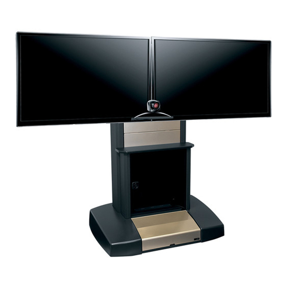
Video Tele-Presence Center
THANK YOU
Thank you for purchasing a Video Tele-Presence Center.
PRODUCT FEATURES
VTC-4280S, VTC-4255D, VTC-5670D
• (6) Front trim panels in Natural Nickel
powder coat finish
• (1) Connectivity Panel with knockouts for:
- (1) UCP LKO
- (6) AVIP LKO's
- (1) 3" Gland Grommet LKO
• (10) Antenna LKO's
• 4 space adjustable height (knobs up) equipment
mounting rails, set at 18" depth inside of uprights
• 2 space (23" usable) rack mounting in lower
hood compartment (front or rear loading) -or-
3 space (16" usable) in lower hood compartment
• Lever Lock™ - (4) LL receptacle brackets,
(2) LL-HC21 horizontal channels and
(1) LL-VP2110 vertical 10" deep plate
• Camera mount
• Middle Atlantic PD-815SC (8) outlet, 15 amp
power strip with surge and circuit breaker
Instruction Sheet
VTC Series
VTC-4280S-R, VTC-4255D-R, VTC-5670D-R
• (6) Front trim panels in Natural Nickel
powder coat finish
• (1) Connectivity Panel with knockouts for:
- (1) UCP LKO
- (6) AVIP LKO's
- (1) 3" Gland Grommet LKO
• (10) Antenna LKO's
• 12 space / 14" depth equipment rack with glass
front door and wood top (VTC-R1214)
• 2 space (23" usable) rack mounting in lower hood
compartment (front or rear loading) -or- 3 space
(16" usable) in lower hood compartment
• Lever Lock™ - (4) LL receptacle brackets,
(2) LL-HC21 horizontal channels and
(1) LL-VP2110 vertical 10" deep plate
• Camera mount
• Middle Atlantic PD-815SC
(8) outlet, 15 amp power strip
with surge and circuit breaker
- MODELS -
• VTC-4280S
• VTC-4255D
• VTC-5670D
• VTC-4280S-R
• VTC-4255D-R
• VTC-5670D-R
I-00579
Rev C
Advertisement
Chapters
Table of Contents

Related Manuals for Middle Atlantic Products VTC Series

Summary of Contents for Middle Atlantic Products VTC Series
- Page 1 Instruction Sheet Video Tele-Presence Center VTC Series - MODELS - • VTC-4280S • VTC-4255D • VTC-5670D • VTC-4280S-R • VTC-4255D-R • VTC-5670D-R THANK YOU Thank you for purchasing a Video Tele-Presence Center. PRODUCT FEATURES VTC-4280S, VTC-4255D, VTC-5670D VTC-4280S-R, VTC-4255D-R, VTC-5670D-R •...
-
Page 3: Important Safety Instructions
IMPORTANT SAFETY INSTRUCTIONS • Clean only with dry cloth Nettoyer avec un chiffon sec seulemen CAUTION! To avoid an unstable condition, place heavier WARNING/CAUTION! The exclamation point within an components at the bottom of the cabinet. When more than equilateral triangle is intended to alert the user to the one component is placed in the cabinet, begin at the presence of important operating and maintenance bottom of the cabinet and place equipment at the lowest... -
Page 4: Table Of Contents
TABLE OF CONTENTS Important Safety Instructions Page 3 Regulatory Compliance Page 3 Introduction Page 5 Weight Ratings Page 5 Mobility Features Page 5 Tools Required Page 5 Hardware / Items Supplied Pages 6-7 Optional Accessories Page 8 Physical Diagrams (VTC-4280S) Page 9 Physical Diagrams (VTC-4280S-R) Page 10... -
Page 5: Introduction
INTRODUCTION This mobile mounting system supports video applications including video conferencing and presentations by safely supporting large-format single (42” – 80”) or dual (42” – 70”) screens. Electronic AV equipment can be mounted in the base and in the main column to support the application, or in the optional 12U rackspace. -
Page 6: Hardware / Items Supplied Pages
HARDWARE/ITEMS SUPPLIED NOTE: Additional hardware may be included FLAT PANEL MOUNTING HARDWARE which may not be required for your installation. M4 x 16 (Qty 8) (Qty 4) M4 x 25 M5 x 12 (Qty 8) 5/16” Flat Washers (Qty 10) M5 x 16 (Qty 6) Single... - Page 7 HARDWARE/ITEMS SUPPLIED (CONTINUED) CONNECTIVITY PANEL FRONT HOOD LOCK CAMERA MOUNT 6-32 KEP Nuts 6-32 x 3/8” (For UCP Knockouts Flat Head Screw Front Hood Lock in Connectivity Panel) 10-32 Flange Nut (For UCP Knockouts Cylinder (Qty 1) Keys (Qty 2) (Qty 4) (Qty 8) in Connectivity Panel)
-
Page 8: Optional Accessories
OPTIONAL ACCESSORIES VTC-4280S-R, VTC-4255D-R, VTC-5670D-R • VTC-DWR-5.5, 5.5” H VTC drawer • LL-VTC-K, Doubles Lever Lock™ capacity = (2) LL receptacle brackets, (2) LL-HC21 horizontal channels and (1) LL-VP2110 vertical 10” deep plate • VTC-WS-32X12SL, 32” W X 12” D Slate finished work surface •... -
Page 9: Physical Diagrams (Vtc-4280S)
PHYSICAL DIAGRAMS (VTC-4280S) VTC-4280S (Front And Side Views) CONNECTIVITY PANEL VTC-4280S (Angled and Rear Views) Page 9... -
Page 10: Physical Diagrams (Vtc-4280S-R)
PHYSICAL DIAGRAMS (VTC-4280S-R) VTC-4280S-R (Front And Side Views) CONNECTIVITY PANEL VTC-4280S-R (Angled and Rear Views) Page 10... -
Page 11: Physical Diagrams (Vtc-4255D / Vtc-5670D)
PHYSICAL DIAGRAMS (VTC-4255D / VTC-5670D) VTC-4255D / VTC-5670D (Front and Side Views) CONNECTIVITY PANEL VTC-4255D / VTC-5670D (Angled and Rear Views) Page 11... -
Page 12: Physical Diagrams (Vtc-4255D-R / Vtc-5670D-R)
PHYSICAL DIAGRAMS (VTC-4255D-R / VTC-5670D-R) VTC-4255D-R / VTC-5670D-R (Front and Side Views) CONNECTIVITY PANEL VTC-4255D-R / VTC-5670D-R (Angled and Rear Views) Page 12... -
Page 13: Rear Access Panel Removal / Installation
REAR ACCESS PANEL INSTALLATION / REMOVAL 1. Rear access panels lift and tilt out. (FIGURE A) 2. Re-install rear access panels in the reverse manner. Rear Access Panels FIGURE A VTC-4280S-R, VTC-4255D-R, VTC-5670D-R VTC-4280S, VTC-4255D, VTC-5670D FRONT HOOD ACCESS 1. Lift front hood up (Hood will remain open). (FIGURE B) 2. -
Page 14: Rack Installation And Removal (-R Models Only)
RACK INSTALLATION AND REMOVAL (-R MODELS ONLY) 1) Remove (2) 6-32 x 3/8” flat head screws securing rear horizontal trim panel to VTC and slide out. (FIGURE C) NOTE: Remove squaring panels from rack only after the first rackmount component has been installed. -
Page 15: Screen Access Panel Removal / Installation
SCREEN ACCESS PANEL REMOVAL / INSTALLATION 1. Remove topmost rear access panel (Refer to REAR ACCESS PANEL INSTALLATION / REMOVAL on page 13). 2. Unfasten (4) wingnuts securing screen access panel to VTC and remove from rear. (FIGURE F) 3. Re-install screen access panel in the reverse manner. Screen Access Panel Screen Access Panel Wingnuts (4) -
Page 16: Flat Panel Installation Pages
FLAT PANEL INSTALLATION 1) Select desired height and NOTE: When installing horizontal mounting bracket, stops must face up mount horizontal mounting bracket to VTC using (4) 5/16”-18 Hex Head Monitor Mount Bolts and (4) 5/16“-18 Flange Nuts. (FIGURE H) NOTE: 1/2” Socket Required NOTE: Screen Access Panel may need to be removed to Horizontal Mounting... -
Page 17: Mounting Bracket
FLAT PANEL INSTALLATION (CONTINUED) Dimples (Face Up) Mounting Screw Universal Washer Mounting Bracket Flat Panel Nylon Spacer Mount Point Attaching Vertical Mounting Brackets to Flat Panel NOTE: Be sure to observe the “up” arrow on each vertical mounting bracket to maintain the proper orientation of the flat panel. - Page 18 FLAT PANEL INSTALLATION (CONTINUED) WARNING! This operation requires two people. Do not release your flat panel until you are certain that the top hook of each vertical mounting bracket is securely seated on the upper rail of the horizontal mounting bracket. Hanging the Flat Panel 1) Remove locking clips from vertical mounting bracket and rotate locking clamps down.
-
Page 19: Camera Mounting (Vtc-4280S / Vtc-4280S-R)
CAMERA MOUNTING (VTC-4280S / VTC-4280S-R) 1) Place vertical camera mounting bracket onto horizontal monitor mounting bracket, ensuring that the top hook is properly engaged. (FIGURE N) NOTE: Observe the “Up” arrow to maintain proper orientation of the vertical mounting bracket. 2) Select desired mounting location (FIGURE O) and secure vertical camera mounting bracket to horizontal monitor mounting bracket using (2) locking screws as shown. -
Page 20: Camera Mounting (Vtc-4255D / Vtc-4255D-R / Vtc-5670D / Vtc-5670D-R)
CAMERA MOUNTING VTC-4255D / VTC-4255D-R / VTC-5670D / VTC-5670D-R 1) Place vertical camera mounting bracket onto horizontal monitor mounting bracket, ensuring that the top hook is properly engaged. (FIGURE S) NOTE: Observe the “Up” arrow to maintain proper orientation of the vertical mounting bracket. 2) Select desired mounting location (FIGURE T) and secure vertical camera mounting bracket to horizontal monitor mounting bracket using (2) locking screws as shown. -
Page 21: Lever Lock™ Tool Free Internal Management System
LEVER LOCK™ TOOL FREE INTERNAL MANAGEMENT SYSTEM The VTC Series comes equipped with the following Lever Lock ™ items: (4) LL receptacle brackets, (2) LL-HC21 horizontal channels, and (1) LL-VP2110 vertical 10” deep plate. Use Horizontal Channels To Manage Cables... -
Page 22: Front Hood Lock Cylinder Installation
FRONT HOOD LOCK CYLINDER INSTALLATION 1) Knock out the lock hole on the front hood. 2) Insert the lock cylinder into the front hood and (FIGURE AA) remove the key in a vertical position. (FIGURE BB) Lock Hole Lock Cylinder Remove Key With Lock In Vertical Position Knockout... -
Page 23: Power Strip Removal / Installation
POWER STRIP REMOVAL / INSTALLATION 1) Remove Lever Lock™ plate and horizontal channels as described in LEVER LOCK™ TOOL FREE INTERNAL MANAGEMENT SYSTEM on page 20. 2) Rotate to unlock the (2) plastic thumbscrews securing each side Lever Lock™receptacle bracket to VTC. FIGURE FF (FIGURE FF) 3) Remove side Lever Lock™... -
Page 24: Warranty
WARRANTY Middle Atlantic Products (the "Company") warrants the Video Tele-Presence Center VTC Series to be free from defects in material or workmanship under normal use and conditions for the lifetime of the product. The Company's entire liability to the purchaser, and the purchaser's (or any other party's) sole and exclusive remedy, under this warranty...
Need help?
Do you have a question about the VTC Series and is the answer not in the manual?
Questions and answers