Advertisement
SPECIFICATION AND INSTALLATION GUIDE
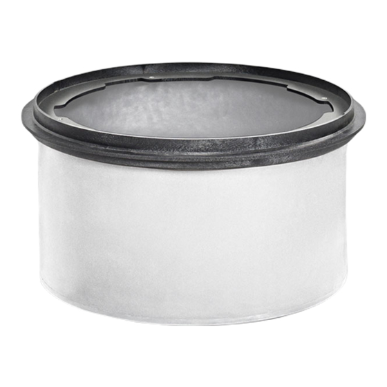
FCR1
Field Cut Riser System
For Use with Grease Interceptors Models
GB1, GB2 and GB3
Contents
Specifications . . . . . . . . . . . . . . . . . . . . . . . . . . . . . . . . . . . . . . . . . . . 1
Special Precautions . . . . . . . . . . . . . . . . . . . . . . . . . . . . . . . . . . . . . 2
Getting To Know The Fcr1 . . . . . . . . . . . . . . . . . . . . . . . . . . . . . . . . 3
Installation . . . . . . . . . . . . . . . . . . . . . . . . . . . . . . . . . . . . . . . . . . . . 4-6
Notes
1.
Rotationally molded polyethylene body
2. Injection molded polypropylene top cover ring
3. EPDM sponge tank-to-riser gasket
4. Silicone fin riser body to riser top gasket
5. Unit weight: 10 lbs.
6. Risers not designed to hold water
Engineer Specification Guide:
Field-cut adjustable riser system to consist of rotationally molded polyethylene
body, injection molded polypropylene top cover ring, EPDM sponge gasket at
bottom, silicone fin gasket at top flange. Risers shall allow field adjustability of
cover to grade.
Installation Note
Minimum install height: 2-1/8". Maximum install height: 12".
Riser system may be stacked no more than two units high to a maximum of 25"
extension. Access to internal components will not be compromised.
9500 Woodend Road | Edwardsville, KS 66111 | Tel: 913-951-3300 | www.schierproducts.com
MODEL NUMBER:
FCR1
PART #: 8010-005-01
DWG BY: B. Karrer
ø 23-3/4"
ø 21-7/8"
ø 21-1/2"
Riser Height Needed
2-1/8" - 12"
>12" - 25"
DESCRIPTION: 12" Field Cut Riser System
DATE: 4/22/2019
12" Max
Extension
12-3/4"
Overall
2-1/8" Min
Extension
Risers Required
FCR1
FCR1 (x2)
REV:
ECO:
© Copyright 2019 Schier, All Rights Reserved
Advertisement
Table of Contents

Summary of Contents for Schier FCR1
- Page 1 FCR1 (x2) Getting to Know the FCR1 ....... . 3 Installation .
- Page 2 SPECIAL PRECAUTIONS For Schier Grease Interceptor Installations - Failure to follow this guidance voids your warranty DO NOT AIR TEST UNIT OR RISER SYSTEM! Do not install this unit in any manner Doing so may result in property damage, personal injury or death.
- Page 3 SPECIAL PRECAUTIONS For Schier Grease Interceptor Installations - Failure to follow this guidance voids your warranty High Water Table Installations Fully Support Base of Unit Install unit on solid, level surface in Interceptors and risers are not designed concrete floor...
- Page 4 GETTING TO KNOW THE FCR1 Cover Ring 4. Riser Body 2. Cover Ring Gasket 5. Riser Mounting Flange 3. Riser Mounting Bolts 6. Riser Body Gasket FCR1 Installation Guide Page 4 of 6...
- Page 5 Finished Grade For the interceptor to be safely and properly maintained, dimension 25" Max A cannot exceed 25" (or two FCR1 risers stacked). 12" Max 1 Riser 2 Risers OPTIONAL: Install Flow Control Extension Handle For easy flow control removal, 1-1/2" PVC SCH. 40...
- Page 6 (about 1"). Prepare for backfill Resume “Buried Installation” instructions for applicable unit (GB1, GB2 or GB3) FCR1 Installation Guide Page 6 of 6...
Need help?
Do you have a question about the FCR1 and is the answer not in the manual?
Questions and answers