Advertisement
Quick Links
u s e r m a n u a l
Fluid Cooler Pump control panel
I N S TA L L AT I O N - O P E R AT I O N - M A I N T E N A N C E
Z0628618_C
I S S UE D 07/ 2014
ISSUED 7/2020
R E AD AN D U N D E R S TAN D T H I S M A N UA L P R I O R TO O P E RAT I N G O R S E R V I C I N G T H I S PR O D U CT.
READ AND UNDERSTAND THIS MANUAL PRIOR TO OPERATING OR SERVICING THIS PRODUCT.
Advertisement

Summary of Contents for Marley Fluid Cooler Pump
- Page 1 Fluid Cooler Pump control panel I N S TA L L AT I O N - O P E R AT I O N - M A I N T E N A N C E...
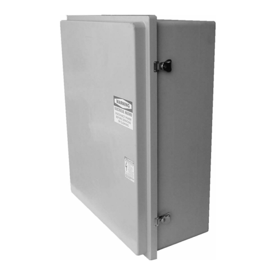
- Page 2 introduction NEMA 4X fiberglass outdoor enclosure with the following features: • Hinged and lockable outer door • Swing-out dead front inner door • Corrosion resistant enclosure Electrical Components • External disconnect handle with padlocking provisions to meet lockout, tag-out safety requirements •...
-
Page 3: Safety First
Safety First The Marley control system uses UL listed components installed in accordance with the National Electric Code. The location of the cooling product and field installation of the control system can affect the safety of those responsible for installing, operating or maintaining the tower and controls. -
Page 4: Installation
Circulating Pump Circuits For the low-water safety circuit connect the two “low water probes”, located in the basin stilling chamber to user terminal points in the control panel. Marley probes are furnished with 20'-0" leads. Refer to the wiring diagram in the control panel for connection points. - Page 5 installation For the freeze safety circuit run two 18 gauge control wires from the thermostat located on the fluid cooler side casing to user terminal points in the control panel. The thermostat has two sets of terminal points. Use either the left or right two points oriented in a vertical column.
-
Page 6: Pump Operation
operation Main Circuit Breaker: Operating handle for the main breaker is located behind the outer door which is pad-lockable for lock out/tag out. Rotating the handle to the OFF position turns power off to the panel. Rotating the handle to the ON position provides power to the control panel. If servicing the panel hot (door open and main breaker in energized position) be sure to align the keyed slot on back of the operating handle with the key on the main breaker shaft before closing the door. - Page 7 Integrated Basin Heater Control Circuit Option The Marley ABHi basin heater package controls the ON and OFF operation of the basin heater device providing freeze protection in the cold-water col- lection basin of the fluid cooler. The stand-alone control package includes a main circuit breaker disconnect that feeds a contactor providing power for the heater element.
- Page 8 operation Solid-state Water Level Control and Alarm Circuit Option The number of probes depends on the number of optional circuits being furnished. Each water level event requires one card. The card includes an on- board relay with (1) form “C” dry contact. Contacts are wired to a user terminal strip for connection to remote devices such as makeup solenoids and alarms.
- Page 12 Fluid Cooler Pump control panel U S E R M A N UA L SPX COOLING TECHNOLOGIES, INC. 7401 WEST 129 STREET Z0628618_C ISSUED 7/2020 OVERLAND PARK, KS 66213 USA ©2009-2020 SPX COOLING TECHNOLOGIES, INC. ALL RIGHTS RESERVED In the interest of technological progress, all products are subject to design 913 664 7400 | spxcooling@spx.com...
Need help?
Do you have a question about the Fluid Cooler Pump and is the answer not in the manual?
Questions and answers