
Summary of Contents for Super Star S1100
- Page 1 S1100 Ventilator Operation Manual Please read the manual carefully before operation.
-
Page 3: Table Of Contents
Contents Remarks of the picture, sign, term and abbreviation in the machine and manual..... 1 Safety item............................. 4 Claim............................... 5 Function............................6 Performance..........................6 Intended use..........................6 Adaption disease...........................6 Contraindication..........................6 EMC Information........................... 7 The main structure and working principle for the ventilator..........12 Main unit........................ - Page 4 System check....................... 26 Check for power supply alarm................... 26 Gas supply check......................27 Ventilation function check................... 27 Check for Alarm function.....................27 Operation............................29 Operation of ventilator....................29 Ventilator panel and operation key................29 Start-up.......................... 30 Selection of VTL or VTHventilation mode..............30 Setting of ventilation mode and parameters............31 Reset of alarm parameter...................
- Page 5 Waste disposal..........................57 Disposal of battery and O2 sensor................57 Disposal of electronic and plastic parts..............57 Scrap disposal of medical equipment...............57 Alarm and disposal system....................... 58 Fault and solution way....................... 64 Main technical specification.......................65 Environment conditions....................65 Classification.........................65 Gas supply........................65 Power supply........................
-
Page 6: Remarks Of The Picture, Sign, Term And Abbreviation In The Machine And Manual
Remarks of the picture, sign, term and abbreviation in the machine and manual “△ ! “indicates you should read the operation manual “ △ ! warning “ and “ △ ! note” indicate if the instruction is not followed, there will be some emergencies, please read and keep to all the “... - Page 7 Picture, sign, term and abbreviation Remarks Equipotential Ground protection Check valve Trigger mark IPPV IPPV SIMV SIMV SPONT/ CPAP SPONT/CPAP MANU or(MAUN) Standby Standby surface nebulizer !!! high priority alarm !! medium priority alarm FiO2 concentration of inhalation MV (Minute Volume) Minute Volume (Tidal Volume)...
- Page 8 Picture, sign, term and abbreviation Remarks Tapn Apnoea time Nebulizer Nebulizer Paw—t Waveform of airway pressure and time Flow—t Waveform of flow and time Power Power concentration adjustment oxygen Vmax Maximum volume BTPS body temperature and pressure-saturated Beat per minute (Unit for frequency ) Second (Unit for time)...
-
Page 9: Safety Item
Safety item “△ ! “ Note: ! Please read the operation manual carefully before operation, assemble, operate, and maintain the machine in strict accordance with the manual. ! Please refer to the chapter of Installation and connection of expiratory flow sensor sampling tube and expiratory valve and O sensor in this manual when install and connect the exhalation flow sensor sampling tube and exhalation valve and O... -
Page 10: Claim
! As using different warning settings and using the same or similar equipment at all the independent area, there may be potentially dangerous. ! Do not disassemble the ventilator without the authorization from Nanjing Super Star Medical Equipment Co., Ltd. -
Page 11: Function
! May be equipped with air compressor。 Intended use S1100 ventilator is applied to various medical institution and used for cardiopulmonary cerebral resuscitation respiratory support, acute respiratory insufficiency or oxygenation function disorder caused by various causes, others need ventilator treatment. It applies for 18 ~ 80 years old patients. -
Page 12: Emc Information
Guidance and manufacturer’s declaration stated in the appendix. Warning: S1100 Ventilator should not be used adjacent to or stacked with other equipment and that if adjacent or stacked use is necessary, S1100 should be observed to verify normal operation in the configuration in which it will be used. - Page 13 Table 1 Guidance and manufacturer’s declaration –electromagnetic emissions The S1100 Ventilator is intended for use in the electromagnetic environment specified below. The customer or the user of the SECP-II should assure that it is used in such an environment. Emissions test...
- Page 14 Guidance and manufacturer’s declaration – electromagnetic immunity The S1100 Ventilator is intended for use in the electromagnetic environment specified below. The customer or the user of the S1100 should assure that it is used in such an environment. IEC 60601 test Electromagnetic environment –...
- Page 15 Guidance and manufacture’s declaration – electromagnetic immunity The S1100 Ventilator is intended for use in the electromagnetic environment specified below. The customer or the user of S1100 should assure that it is used in such an environment. Complianc Immunity test...
- Page 16 RF communications equipment and the S1100 Ventilator The S1100 Ventilator is intended for use in an electromagnetic environment in which radiated RF disturbances are controlled. The customer or the user of the S1100 Ventilator can help prevent...
-
Page 17: The Main Structure And Working Principle For The Ventilator
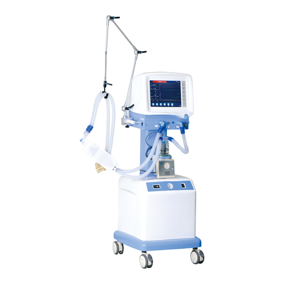
Main unit Structure The S1100 ventilator is made up of main unit (including Ventilation parameters setting, monitoring, control and display system, Gas source input port, Patients connector, Oxygen concentration monitoring and O and air blending system) and Air compressor(optional), rack (the overall... - Page 18 (without compressor) 1Parameter display screen 2 panel and Air blender adjusting knob 4 Humidifier Bracket 5 Main frame 6 Castor 7 Air Compressor 8 Inhalation port 9 nebulization port 10 Exhalation port 11 Air input port 12 O input port 14 ~220V power input socket/Fuse box 13 compressor fuse box 15 Auxiliary socket...
-
Page 19: Working Principle
Working Principle Fig 2 Graph for working principle The gas source passes O and air blender,then respectively enters nebulier controlling valve, flow controlling valve and exhalation controlling valve. During inhalation, flow controlling valve and exhalation controlling valve open, while the exhaling valve closes. -
Page 20: Air Compressor (If Equipped With Air Compressor)
open for inhalation, so that the patient can breath the air from atmosphere. Air compressor (if equipped with air compressor) Structure 1 Timer 2 Output gas pressure gauge 3 Run indicator 4 Alarm indicator 5 Switch 6 Input gas filter net 7 Output gas port Fig 3 air compressor structure Working Principle... -
Page 21: Preparation
Preparation Gas supply connection △ ! Note: 1 The rated working pressure of ventilator is 400kPa±20kPa,and the maximum flow is 70L/min。 2 The gas source should be specialized for medical usage. Be aware the impurity from the central gas pipe when use the central gas supply as gas source. -
Page 22: Air Connection
Air connection cylinder (if equipped with air ! This machine can use central gas supply or high-pressure O compressor)as gas source; ! Check that the pressure of gas source from air compressor or central gas supply must accord with requirement of this machine; ! See Fig 5,connect filter 2 and Connector 3(the flow direction of filter face the machine);... -
Page 23: Connection Of Breathing Circuit Pipe
Connection of breathing circuit pipe △ ! Note: 1.Never use the antistatic breathing tube and facemask. It may be cause inflammation if use this kind of breathing tube and face mask near the high frequency electric operation equipments 2 breathing circuit equipped on ventilator should meet the standards ISO 5367. Refer Fig 7 for breathing circuit pipe connection 1 Exhalation port 2 Breathing tube 1... -
Page 24: The Installation And Connection Of Exhalation Valve
The installation and connection of exhalation valve The exhalation valve is installed already on the machine before leaving factory. If you need to re-install them, please follow the following steps and refer to Fig 8. Install the exhalation valve, cover, and exhalation connector in turn from Direction. Do not leak the gas. -
Page 25: Installation Of Humidifier
Fig 9 The installation and connection of O sensor Installation of humidifier Refer Fig 10 for installation and connection of humidifier. (with compressor) (without compressor) 1 Humidifier 2 Bracket Fig.10 Installation of humidifier Installation of nebulizer △ ! Warning: nebulizer should be registered in national or provincial medical administration. ——connection of nebulizer port and nebulization port(Item 9 Fig1). -
Page 26: Installation And Use Of Pressure Regulator
Installation and use of pressure regulator Installation and use △ ! Warning: 1) Please make sure that O pressure regulator is only compatible with O cylinder. 2 ) If there is any grease on the O pressure regulator or the O cylinder output port, the explosion will be caused. -
Page 27: Power Supply
Power supply Warning: : : 1 IEC 60601-1-1 is applicable to connection of all medical devices and the connection between least one medical device with one or more nonmedical devices. The nonfunctional connection on an auxiliary net power socket between the separate parts of the device will come into the medical electronic system.. -
Page 28: Main Power Supply
Main power supply -----Backup battery transition ! It will switch over to backup battery automatically when the main power supply fails during operation. ! When the back-up battery power the ventilator, there is sound indication from the machine, and the power state indication place will display the signal of “ ”. -
Page 29: Replacing Of The Back-Up Battery
Replacing of the back-up battery ! Usually, the battery can be used for 3- 6 years, if it is often used in over voltage state, or often power cut or the environment temperature is excessive high, efficiency will become lower the and life will be shorten. - Page 30 ! Fuse replacing for compressor power(If equipped with compressor) ——When the input AC power is normal, open the switch(Item 5 in Fig 3),the compressor doesn’t work while the mainframe is normal, you should check the fuse (Model: 5T-6.3AL250V) of compressor fuse box(Item 13 in Fig 1); ——Cut off the main power supply and open the fuse box by screwdriver to replace the fuse if it is damaged.
-
Page 31: Check Before Operation
Check before operation △ ! Warning: In order to ensure the excellent performance in operation, the safety feature and ventilation function must be checked before operation. Do not use machine with problem. If there is alarm from the machine, do not use it, for machine may be damaged, or the patient may be injured. -
Page 32: Gas Supply Check
Gas supply check ! The gas pressure of central gas supply should be 440 kPa±160 kPa (280 kPa~600 kPa) ! If take air cylinder as gas source, the gas in the air cylinder should be full or enough for operation and the output pressure of the pressure regulator should be 400kPa±20 kPa. ! If the compressor is equipped, switch on the compressor (Item 5 in Fig 3), pressure gauge on the compressor panel should be 400kPa±20 kPa when the compressor is working stably. - Page 33 there is an alarm for High Ppeak, the pressure should be limited under 20 cmH Check for low Ppeak alarm: ——Set the low limit of Ppeak alarm to 10 cmH ——Reset the tidal volume to make Ppeak under the low limit; ——When the Ppeak is under the low limit, there will be an alarm for low Ppeak alarm.
-
Page 34: Operation
Operation △ ! Warning: 1)This machine can only be operated by special qualified personnel after training. 2)Please read the operation manual carefully before operation. And operate the machine in strict accordance with the manual. 3)This machine can only be used under close observation. Though clinical safety has been fully considered in the design of this machine, the operator should not neglect the observation of the machine status and the patient. -
Page 35: Start-Up
Start-up ! Connect the power supply and gas source ! Switch on the ventilator switch, then the machine will enter the self-check surface. ! When self-check is finished, the machine will enter VT ventilation mode selection surface. Refer to Fig 13. Fig 13 VT ventilation mode selection surface Selection of VT... -
Page 36: Setting Of Ventilation Mode And Parameters
Setting of ventilation mode and parameters ! Enter the surface of setting of ventilation mode and parameters ——Choose mode, and press confirmation key; ——Press ventilator setting key (Item 3 in Fig 12) in working surface, you can reset ventilation mode and parameters. ——Fig . - Page 37 Fig 16 Setting of mode and parameter under A/C Fig 17 Setting of mode and parameter under SIMV Fig 18 Setting of mode and parameter under SPONT/CPAP Fig 19 Setting of mode and parameter under PSV...
-
Page 38: Reset Of Alarm Parameter
Reset of alarm parameter ! Reset of alarm parameter: ——Press alarm setting key (Item 5 in Fig 12), the machine will enter Reset of alarm parameter surface. Refer to Fig 20. ! Reset of the alarm parameter value: ——Turn shuttle (Item 8 in Fig 12) to the parameter to be adjusted; ——Press shuttle for confirmation;... -
Page 39: Reset Of System Setting
Fig 21 Reset of alarm parameter surface(two) Hint: Only under the modes of SIMV、SPONT/CPAP、PSV, apnea time can be set. Reset of system setting ! Reset of system setting: ——enter the relevant surface of ventilation mode,if do not use previous mode or default system setting, can do reset of system setting;... -
Page 40: Start Up For Operation--Ippv Ventilation Mode
Start up for operation——IPPV ventilation mode ! Enter IPPV mode: ——Choose IPPV mode under the surface of ventilation mode and parameter setting in Fig. 14; ——Press Shuttle(Item 8 in Fig12)for confirmation and machine will enter standby status; ——Turn shuttle (Item 8 in Fig12)to “ ”, and press it for exit, and the machine will work under mode of IPPV. - Page 41 Illustration for the surface: ——(1) is Alarm audio paused indication place. ——(2) is respectively indication place for alarm of High continuous pressure, High (Low) Airway pressure, High (Low) O concentration, High (Low) MV, No tidal volume. ——(3) is place for manual ventilation lock or unlock indication. ——(4) is indication for the trigger condition (this mode is no trigger).
-
Page 42: Start Up For Operation--Pcv Ventilation Mode
Start up for operation——PCV ventilation mode ! Enter the mode of PCV: ——Choose mode PCV under the surface of ventilation mode and parameter setting in Fig. 15; ——Press Shuttle(Item 8 in Fig12) for confirmation and machine will enter standby status; ——Turn shuttle (Item 8 in Fig12) to“... - Page 43 Illustration for the surface: ——(1) is Alarm audio paused indication place. ——(2) is respectively indication place for alarm of High continuous pressure, High (Low) Airway pressure, High (Low) O concentration, High (Low) MV, No tidal volume. ——(3) is place for manual ventilation lock or unlock indication. ——(4) is indication for the trigger condition (this mode is no trigger).
-
Page 44: Start Up For Operation--A/C Ventilation Mode
Start up for operation——A/C ventilation mode ! Enter the mode of A/C ——Choose mode A/C under the surface of ventilation mode and parameter setting in Fig. 16; ——Press Shuttle(Item 8 in Fig12) for confirmation and machine will enter standby status; ——Turn shuttle (Item 8 in Fig12) to“... - Page 45 Illustration for the surface: ——(1) is Alarm audio paused indication place. ——(2) is respectively indication place for alarm of High continuous pressure, High (Low) Airway pressure, High (Low) O concentration, High (Low) MV, No tidal volume and Apnea. ——(3) is place for manual ventilation lock or unlock indication. ——(4) is indication for the trigger condition (this mode is no trigger).
-
Page 46: Start Up For Operation--Simv Ventilation Mode
Start up for operation——SIMV ventilation mode ! Enter the mode of SIMV: ——Choose mode SIMV under the surface of ventilation mode and parameter setting in Fig. 17; ——Press Shuttle(Item 8 in Fig12) for confirmation and machine will enter standby status; ——Turn shuttle (Item 8 in Fig12) to“... - Page 47 Illustration for the surface: ——(1) is Alarm audio paused indication place. ——(2) is respectively indication place for alarm of High continuous pressure, High (Low) Airway pressure, High (Low) O concentration, High (Low) MV, No tidal volume and Apnoea. ——(3) is place for manual ventilation lock or unlock indication. ——(4) is the trigger condition.
-
Page 48: Start Up For Operation--Spont/Cpap Ventilation Mode
Start up for operation——SPONT/CPAP ventilation mode ! Enter the mode of SPONT/CPAP: ——Choose mode SPONT/CPAP under the surface of ventilation mode and parameter setting in Fig. 18; ——Press Shuttle(Item 8 in Fig12) for confirmation and machine will enter standby status; ——Turn shuttle (Item 8 in Fig12) to“... - Page 49 Illustration for the surface: ——(1) is Alarm audio paused indication place. ——(2) is respectively indication place for alarm of High continuous pressure, High (Low) Airway pressure, High (Low) O concentration, High (Low) MV, No tidal volume and Apnoea. ——(3) is place for manual ventilation lock or unlock indication. ——(4) is the trigger condition (the mode is non-trigger).
-
Page 50: Start Up For Operation--Psv Ventilation Mode
Start up for operation——PSV ventilation mode ! Enter the mode of PSV: ——Choose mode PSV under the surface of ventilation mode and parameter setting in Fig. 19; ——Press Shuttle(Item 8 in Fig12) for confirmation and machine will enter standby status; ——Turn shuttle (Item 8 in Fig12) to“... - Page 51 ——(1) is Alarm audio paused indication place. ——(2) is respectively indication place for alarm of High continuous pressure, High (Low) Airway pressure, High (Low) O concentration, High (Low) MV, No tidal volume and Apnoea. ——(3) is place for manual ventilation lock or unlock indication. ——(4) is the trigger condition.
-
Page 52: Start Up For Operation--Manu Ventilation Mode
will have indication of “ ”. The machine will stop gas supply if you do not press the MANU key. Start up for operation——Apnoea function hint:Only under the ventilation mode of SIMV、SPONT/CPAP、PSV,apnoea time can be set. ! Before Choose of apnoea mode, please set the proper ventilation parameters under the mode of A/C. -
Page 53: Start Up For Operation--Audio Paused Function
key“ ” (item2 in Fig. 12).after audio paused time (2 minutes),alarm will remain unless the problem is solved properly. ! When the sound alarm is audio paused, the alarm indication“ ” on the sreen will remain unless the problem is solved properly. Start up for operation——key lock function ——Under the every ventilation mode,press system setting key (item4 in Fig.12),enter system setting surface;... -
Page 54: Oxygen Concentration Calibration
——press shuttle(Item 8 in Fig12)to enter “ ” surface, refer to Fig 31; ——Turn shuttle (Item 8 in Fig12)to “21%”and press it till the indication “Complete ”will be on the screen; ——Turn shuttle (Item 8 in Fig12)to “100%”and press it till the indication “Complete ”will be on the screen;... -
Page 55: Alarm, Warning And Hint Information
Alarm, warning and hint information △ ! Warning: 1)If there is alarm during operation, safeguard the patient firstly, then check immediately to fix the fault. 2)As to the alarm of humidifier, please refer to the operation manual of humidifier. Please refer to table 2 of the alarm and warning information. Table 2 Alarm and warning information Alarm and warning information Cause of alarm and warning... - Page 56 Please refer to table 3 of the hint information. Table 3 Hint information Hint information Meaning of hint information Power supply by main power Audio paused Lock Unlock High MV mode Low MV mode Trigger mark Manual ventilation...
-
Page 57: Clearance And Disinfection
Clearance and disinfection △ ! Warning: 1) Do not use talc, zinc stearate, CaCO , cornstarch or similar material, which will enter the lung or Respiratory tract of the patient. 2) Any liquid into the machine may lead to electric shock or damage to the machine. △... -
Page 58: Clearance And Disinfection Of Reusable Part
Clearance and disinfection of reusable part The reusable parts of this machine include Breathing circuit pipes with Y connector, inhalation port, exhalation port, exhalation valve, tidal volume sampling tube and water trap. Process for clearance and disinfection after operation: ! Remove the parts from the machine; ! Wash the parts by soapsuds;... -
Page 59: Maintenance
Maintenance △ ! Warning: 1) Do not use machine with problem. 2) The machine can only be repaired by authorized personnel. If the user needs to repair,,This machine can only be operated by special qualified personnel after training. When necessary, our company can provide the necessary information 3)... -
Page 60: Every Three Months Or Over 1000 Hours
Every three months or over 1000 hours If equipped with air compressor ! Every three months or over 1000 hours,wash the sponge in the round filter( Item 1 Fig 32)by one time. ! Take off the back panel by cross screwdriver. ! Take off the round filter and remove the cover. -
Page 61: Every Year Or Operation Over 2500 Hours
Every year or operation over 2500 hours ! Maintain, and check the machine completely; ! Replace the gasket and O type circle; ! Replace the input gas filter net ( Item 6 Fig 3)of the compressor ( if equipped with air compressor)... -
Page 62: Waste Disposal
Waste disposal Disposal of battery and O sensor △ ! Warning Do not throw the battery or O sensor into the fire in case of explosive; Do not open or destroy the them, because it contains injurant which may injure skin and eyes. Please dispose the battery under the local environment law. -
Page 63: Alarm And Disposal System
Alarm and disposal system △ ! Warning: 1) If there is alarm during the operation, safeguard the patient firstly, then check immediately to fix the fault. 2) If there’s failure during operation, and the machine stop working, please do manual ventilation to the patient. - Page 64 ! Alarm information: Alarm Priority Setting range Default value Alarming way When the monitoring value over the upper limit of Ppeak, there 20 ~ 100 cmH High Ppeap alarm High 40 cmH will be a sound alarm and display “High Ppeak!!!”.
- Page 65 Alarm Priority Setting range Default value Alarming way When the monitoring value of O concentration under low limit of O Low O alarm High 18%~99% concentration, there will be a sound alarm and display “ O low!!!”. If the airway pressure (PEEP+15 cmH 0)...
- Page 66 Alarm Priority Setting range Default value Alarming way Main power disconnection or problem, the machine Power failure power supply will be alarm battery, there will be a sound alarm and display of “ ”. When the voltage of back-up battery is low (11V±0.3V), the power Low voltage alarm Medium...
- Page 67 ! Cause of alarm and solution of the alarm: Alarm Cause Solution of alarm 1 Block of breathing circuit pipe 1 Check the breathing circuit pipe 2 Block of patient airway. 2 Check the patient status High Ppeak 3 Upper limit of alarm is too low. 3 Re-set the upper limit of alarm.
- Page 68 Alarm Cause Solution of alarm 1 Problem with breathing circuit pipe 1 Check and reconnect the pipe 2 Block of patient airway 2 Check the patient status Continuous 3 Alarm limit of is too low 3 Reset the alarm limit pressure alarm 4 Ventilation parameters are set 4 Reset the ventilation parameters...
-
Page 69: Fault And Solution Way
Fault and solution way Cause to the fault and solution way: Fault Cause Solution way There is no display 1 The main power is off 1 Check the power supply in the working on screen and 2 Power line disconnection place ventilator do not 3 The starting switch is off. -
Page 70: Main Technical Specification
≤93 % Relative humidity Atmospheric pressure 500 hPa~1060 hPa Classification Classified according to IEC60601-1,S1100 belong to: ! Class I equipment、internally powered equipment; ! Category B equipment; ! Common equipment; ! Continuous operation; ! please refer to the Chapter “clearance and disinfection”... -
Page 71: Electromagnetism Compatibility
Electromagnetism compatibility △ ! Warning: 1) Cell phone and other radiation equipment used near the machine will cause unexpected problem to the ventilator. If there is radio frequency radiation source nearby,working status of the equipment should be monitored. 2) The other equipment added to ventilator will lead to disturbance to the machine. Before used to the patient, check if the machine work normally under the set values. -
Page 72: Humidifier
Humidifier ! Pressure and flow table Flow(L/ min) Pressure(kPa) 0.02 0.03 0.04 0.05 0.07 0.12 ≤0.01L/ kPa ! Compliance: ≤0.6L ! Internal capacity: Remarks:The above mentioned data are based on the humidifier of Infinium. Ventilation mode ——IPPV ——A/C ——PCV ——SIMV ——SPONT/ CPAP ——PSV ——SIGH... - Page 73 ——Max MV ≥18 L/min ≥10 L/min ! PEEP O ~ 40 cmH ——Adjusting range 0 cmH ±(2 cmH ——Allowable error O + 5% setting valve) ! CPAP O ~ 20 cmH ——Adjusting range 0 cmH ±(2 cmH ——Allowable error O + 5% setting valve) ! Continuous flow 7 L/min ~...
-
Page 74: Ventilation Parameter Monitoring Range
! Max set working pressure (pressure limit range) O ~ 100 cmH 20 cmH ≤125 cmH ! Max pressure ! Output MV under manual ventilation ≥25L/min ! Nebulizer gas maximum output pressure≤0.2 MPa maximum output flow≥8 L/min explanation: 1) set pressure limit value to produce maximum working pressure( the upper limit of high airway pressure alarm). -
Page 75: Technical Specification Of Air Compressor
! the purpose 、sensor position 、type and sampling method of control 、measurement and display device the purpose sensor position type sampling method Choose average value pressure- voltage、Simulated data Airway pressure Exhaling end from multiple sampling Choose average value PEEP Exhaling end pressure- voltage、Simulated data from multiple sampling Contionous... -
Page 76: Alarm Hint And Protection
Alarm hint and protection ! Main power failure alarm When the power is supplied by AC, the power state indication place will display the signal of “ ”.When the power is changed from AC to back-up battery , there will be a sound alarm, and the power state indication place will display the signal of “... - Page 77 ! Continuous pressure alarm If the airway pressure ( PEEP+15 cmH O ) over the upper limit or under low limit of continuous pressure alarm in 16 seconds, there will be a sound alarm and display “Pcon high !!!” ! High or low O concentration alarm When the monitoring value of O concentration over the upper limit of O...
-
Page 78: Move, Storage And Transportation
Move, storage and transportation Move △ ! Note: Keep the balance and stable of the machine when move the ventilator. ! Before the move, all the power line and breathing circuit pipes should be pull out from the machine. ! Keep the balance and stable of the machine when move the ventilator. Storage ! The anesthesia apparatus shall be stored indoors with ambient temperature of -20℃~50℃, relative humidity not exceeding 93%... -
Page 79: Appendix:installation Diagram
Appendix : : : Installation diagram (with compressor) Name Specification Remark Ventilator 2.782.074A Packing box 1 Serrated saddle φ5 Screw M5×12 Bracket base 4.142.013A packing box2(they have already assembled together) Air Compressor 2.782.076A Fig.33 Installation diagram 1... - Page 80 (without compressor) Name Specification Remark Ventilator 2.782.074A Packing box 1 Serrated saddle φ5 Screw M5×12 packing box2(they have already Main frame 8.039.017 assembled together) Fig.34 Installation diagram 2...
- Page 81 Name Specification enclose 8.074.018 main frame 8.039.017 connection plate 8.610.191 handle 8.333.006 8.039.001 handle pillar dustband 8.683.024 screw M4X10 screw M6X45 screw M10X35 spring washer Φ6 spring washer Φ10 flat gasket Φ10 Fig.35 Installation diagram 3...
- Page 82 2.782.027AS-A 2016.09.05 Thank you for choosing S1100 ventilators Please read this manual before operation , and keep it for inspection...
Need help?
Do you have a question about the S1100 and is the answer not in the manual?
Questions and answers