Table of Contents
Advertisement
Quick Links
Advertisement
Table of Contents

Summary of Contents for VIPA TD 03
- Page 1 Manual VIPA HMI TD 03 Order no.: VIPA HB116E_TD03 Rev. 07/50...
- Page 2 Lerrzeichen...
- Page 3 Manual VIPA HMI About this manual The information in this manual is supplied without warranties. Information is subject to change without notice. © Copyright 2007 VIPA, Gesellschaft für Visualisierung und Prozess- automatisierung mbH Ohmstraße 4, D-91074 Herzogenaurach, Tel.: +49 (91 32) 744 -0 Fax.: +49 (91 32) 744-144...
- Page 4 Deployment of the TD 03 Main theme of this chapter is the deployment and the project engineering of the TD 03. It contains information about the assembly, the connection and the general handling of the TD 03. The chapter closes with a short description of TD-Wizard, the project engineering tool from VIPA and with information about firmware updates.
-
Page 5: Table Of Contents
Project engineering - Overview ............2-5 Project engineering - Deployment TD-Wizard ........2-6 Commissioning................... 2-15 Operating the TD 03 - Overview............2-17 Operating the TD 03 - Menu mode............. 2-18 Firmware update of the TD 03............2-22 Chapter 3 General installation guidelines ........3-1 Basic rules for the EMC-equitable assembly of installations.... - Page 6 Contents Manual VIPA HMI HB116E - TD03 - Rev. 07/50...
-
Page 7: User Considerations
Manual VIPA HMI User considerations User considerations This manual describes the Text Display TD 03 from VIPA. It describes the Objective and installation, project engineering, usage and the technical data. contents Target audience The manual is targeted at users who have a background in automation technology and PLC programming. -
Page 8: Safety Information
Safety information The Operation devices are constructed and manufactured for: Application specifications • VIPA CPUs 11x, 21x, 31x, 51x and S7-300/400 from Siemens • communication and process control • industrial applications • operation within the environmental conditions specified in the technical... -
Page 9: Chapter 1 Hardware Description
Chapter 1 Hardware description Chapter 1 Hardware description In this chapter the hardware components of the TD 03 are described. Overview Besides of a description of the single components, the dimensions that are required for the installation may also be found. The chapter closes with the technical data. -
Page 10: Safety Information For Users
Chapter 1 Hardware description Manual VIPA HMI Safety information for Users VIPA modules make use of highly integrated components in MOS- Handling of technology. These components are extremely sensitive to over-voltages electrostatic that can occur during electrostatic discharges. sensitive modules... - Page 11 Manual VIPA HMI Chapter 1 Hardware description Shipping of Modules have to be shipped in the original packing material. electrostatic sensitive modules Measurements When you are conducting measurements on electrostatic sensitive modules you should take the following precautions: and alterations on •...
-
Page 12: Properties
The project engineering happens in the projecting tool TD Wizard from VIPA. TD Wizard creates a data block containing your presetting that may be accessed by the CPU at need after the connection of the TD 03. • Die-cast aluminum case Properties •... -
Page 13: Structure
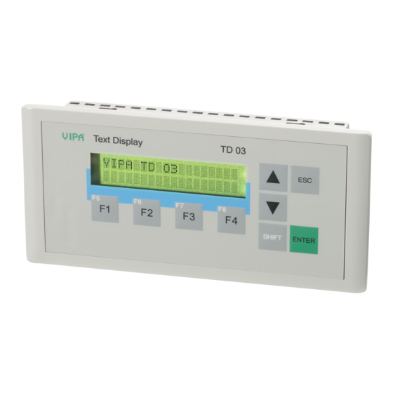
Manual VIPA HMI Chapter 1 Hardware description Structure At the front side of the text display TD 03 is the foil keyboard and the Front view display with 2x20 characters. Display Text Display TD 03 Function keys Navigation keys SHIFT ENTER At the TD 03 the connectors are located at the backside. - Page 14 Chapter 1 Hardware description Manual VIPA HMI Components The TD 03 monitors values and messages via a STN text display with LED LC-Display back lighting. It displays 2 rows with max. 20 characters with a line height of 5mm. Keyboard At the front side is a foil keyboard with 9 short click keys.
-
Page 15: Dimensions
Manual VIPA HMI Chapter 1 Hardware description Dimensions Installation For the installation of the TD 03, an installation cutting with the dimensions 156mm x 78mm is required. dimensions Installation values for control cabinets and desks: Front panel width: max. 6mm... -
Page 16: Technical Data
Chapter 1 Hardware description Manual VIPA HMI Technical data TD 03 - Text Display Electrical data VIPA 603-1TD00 Nominal supply voltage DC 24V (20.4 ... 28.8V) Current consumption max. 80mA Max. inrush current 3A, 10µs (at 30V) ESD/Burst Acc. IEC 61000-4-2 / IEC 61000-4-4 (up to level 3) Shock resistance Acc. - Page 17 Project engineering - Overview ............2-5 Project engineering - Deployment TD-Wizard ........2-6 Commissioning................... 2-15 Operating the TD 03 - Overview............2-17 Operating the TD 03 - Menu mode............. 2-18 Firmware update of the TD 03............2-22 HB116E - TD03 - Rev. 07/50...
-
Page 18: Fast Introduction
Chapter 2 Deployment TD 03 Manual VIPA HMI Fast introduction Installation Build the CPU system and install the TD 03. For the installation in operating tables and control cabinet fronts a front panel cutting of 156mmx78mm (LxW) is needed. Configuration From the software side the connection to the CPU system happens by a data block. -
Page 19: Chapter 2 Deployment Td 03
CPU. Connect the CPU und the TD 03 by the delivered cable 670-0KB00. As soon as the TD 03 is connected to the CPU, it is automatically started up. TD 03... -
Page 20: Installation
[2]. Now bolt the lever [5] clockwise with the screwdriver [4] until it rotates to the outside. Further screwing bolts the lever to the front panel until it holds the TD 03 to the control cabinet front. HB116E - TD03 - Rev. 07/50... -
Page 21: Project Engineering - Overview
The text display TD 03 is projected with the TD-Wizard. This creates a data block that is accessed from the CPU after the TD 03 has been logged in. The data block contains all information required from the CPU like e.g. data areas and message texts that are necessary for the operation of the TD 03. -
Page 22: Project Engineering - Deployment Td-Wizard
You may import the data block in the SIMATIC Manager from Siemens into your project and load it to the CPU. After the link-up of the TD 03 with valid MPI parameters, the according DB contents are transferred from the CPU to the TD 03. - Page 23 Manual VIPA HMI Chapter 2 Deployment TD 03 The TD 03 can monitor menu options and entry requests in a configurable Language and language and the according character set. The here chosen language has character set no influence on the text of the user defined message texts that are displayed by the TD 03.
- Page 24 If you activate this menu option you may force selected in- res. outputs via Menu option the TD 03, i.e. freeze them at a defined state. Forcing takes place at the Force variables beginning and at the end of a cycle. During the cycle, forcing is deactivated.
- Page 25 Manual VIPA HMI Chapter 2 Deployment TD 03 The TD 03 is provided with 8 function keys (F1 to F4 and SHIFT F1 to Function keys and SHIFT F4) that allow you access to the bit memory area in the CPU. As...
- Page 26 A 20-character-message uses 20Byte in the data block of the CPU. Every message is shown in one row of the TD 03. That allows to display two messages at one time. A 40-character-message uses 40Byte in the data block. Only one message can be displayed at a time.
- Page 27 Set the start address from where on the parameter block with the size 10Byte will be stored in the DB. Per default the setting DBB 0 is used. To display a message on your TD 03, your user application has to set an "Enable flags"...
- Page 28 Chapter 2 Deployment TD 03 Manual VIPA HMI This dialog window allows you to enter the text for the messages. The Create messages content of the window depends on the number of characters that you've set as standard size (20 or 40 characters).
- Page 29 Manual VIPA HMI Chapter 2 Deployment TD 03 Data format So that the data value may be displayed, place for the data value and the associated format should be reserved within the message. Start anchor for the data value is the most right character of the value.
- Page 30 Chapter 2 Deployment TD 03 Manual VIPA HMI Structure of the The format word precedes the embedded data value and occupies 2 Format-Word positions (Byte) in the DB: Byte Bit 7 ... Bit 0 Bit 0: (A) Acknowledgement 0 – No acknowledgement 1 –...
-
Page 31: Commissioning
670-0KB00 via the MP I jack. Here the panel may not be supplied additionally externally. As soon as the power supply of the CPU is switched on, the TD 03 is supplied with DC 24V via MPI and starts automatically. Power supply only... - Page 32 CPU. • Connect the CPU und the TD 03 via MPI interface by the delivered cable 670-0KB00. As soon as the TD 03 is connected to the CPU, it is automatically started up.
-
Page 33: Operating The Td 03 - Overview
• Menu mode Display mode After the start, the TD 03 is in display mode. The display mode is the standard operating mode of the TD 03. Here you may switch between the activated messages respectively acknowledge them and alter process values. -
Page 34: Operating The Td 03 - Menu Mode
TD 03 in the display mode switches to the menu mode. So far as there is no DB in the CPU concerning the TD 03 the menu is displayed in English. If you don't push another key within 1 min., the panel switches back to the display mode. - Page 35 CPU Address and set the MPI address of your CPU. For the TD 03 receives its data from a CPU data block, you may store several data blocks in the CPU. Via the entry "Parameter Block" you define the wanted DB via its number.
- Page 36 CPU. The TD 03 switches back to display mode. Note! The TD 03 does not proof the correctness of date and time. You may also enter invalid dates into the CPU. This menu option is only available if enabled in the TD-Wizard. You may Force I/Os also protect this function with a password.
- Page 37 The TD 03 allows you to lock the menu mode and the value setting via a Lock via password. The password is entered in the TD-Wizard. You activate the...
-
Page 38: Firmware Update Of The Td 03
Manual VIPA HMI Firmware update of the TD 03 Overview The TD 03 allows you to update the firmware via an update software and the Green Cable from VIPA. The 2 last recent firmware versions can be downloaded in the service area of www.vipa.de and from the ftp server ftp.vipa.de. -
Page 39: Firmware Update Of The Td 03
2. Turn off the power supply of your TD 03, push the key and turn on the power supply again. Now the TD 03 is ready for the firmware update. Nothing is shown on the display. to 3. Click on in the updater. - Page 40 Chapter 2 Deployment TD 03 Manual VIPA HMI 2-24 HB116E - TD03 - Rev. 07/50...
-
Page 41: Chapter 3 General Installation Guidelines
Manual VIPA HMI Chapter 3 General installation guidelines Chapter 3 General installation guidelines "With General installation guidelines" you get information about the Overview interference-immune installation of Programmable Logic Controls (PLC). Here we describe possible paths in which interference can enter the controller, how you ensure the electromagnetic compatibility (EMC) and how to approach shielding and screening issues. -
Page 42: Basic Rules For The Emc-Equitable Assembly Of Installations
Chapter 3 General installation guidelines Manual VIPA HMI Basic rules for the EMC-equitable assembly of installations The term electromagnetic compatibility (EMC) refers to the ability of an What is EMC? electrical device to operate properly in an electromagnetic environment without interference from the environment or without the device causing illegal interference to the environment. - Page 43 Manual VIPA HMI Chapter 3 General installation guidelines Coupling The following table shows the four different coupling mechanisms, their causes and possible interference sources. mechanisms and interference sources Coupling mechanism Cause Typical source • Pulsed devices Galvanic or metallic coupling...
- Page 44 Chapter 3 General installation guidelines Manual VIPA HMI Basic rules for In many cases, adherence to a set of very elementary rules is sufficient to ensure EMC. For this reason we wish to advise you to heed the following ensuring EMC...
- Page 45 Manual VIPA HMI Chapter 3 General installation guidelines In critical cases you should implement special EMC measures • Connect suppressors to all inductive loads that are not controlled by special EMC-modules. • Use incandescent lamps for illumination purposes inside cabinets or cubicles, do not use of fluorescent lamps.
-
Page 46: Emc-Equitable Assembly
Chapter 3 General installation guidelines Manual VIPA HMI EMC-equitable assembly Mostly, measures for suppressing interference voltages are only taken, when the control is already in commission and the perfect receive of a wanted signal is disturbed. Causes for such interference's are in the most cases inadequate reference potentials, coming from mistakes at the device assembly and installation. -
Page 47: Emc-Equitable Cabling
Manual VIPA HMI Chapter 3 General installation guidelines EMC-equitable cabling Content of this section is the line routing of bus, signal and supply lines. Line routing Object of the line routing is to suppress the "slurring" at parallel lines. Line routing inside... - Page 48 • Install these protective elements at the location where the cables enter the building. Note! Any lightning protection system must be based on an individual assessment of the entire plant. For questions please contact VIPA GmbH. HB116E - TD03 - Rev. 07/50...
- Page 49 Manual VIPA HMI Chapter 3 General installation guidelines Equipotential Potential differences may occur between different sections when controllers and peripheral equipment are connected by means of non- bonding isolated connections or the screens of screened cables are connected at both ends and grounded on different sections of the plant.
- Page 50 Chapter 3 General installation guidelines Manual VIPA HMI One-sided In exceptional cases it may be necessary to ground the screen on one side only. However, this will only attenuate the lowest frequencies. The one- grounding of sided grounding of screens may provide advantages when: screens •...
-
Page 51: Special Precautions Providing High Noise Immunity
Manual VIPA HMI Chapter 3 General installation guidelines Special precautions providing high noise immunity Inductors controlled by your programmable controller (e.g. contactors and Inductors require relays) do not normally require suppressors as the respective modules suppressors have been provided with the required components. -
Page 52: Checklist For The Emc-Compliant Installation Of Controllers
Chapter 3 General installation guidelines Manual VIPA HMI Checklist for the EMC-compliant installation of controllers Space for Notes EMV-measures Connection of the inactive parts You should take special care to check the connections of: • Module racks • Frames • Screen and protected earth conductor... -
Page 53: Index
Manual VIPA HMI Index Appendix Index Commissioning ......2-15 Menu mode......... 2-18 Connection........2-15 Messages ......2-10, 2-12 Contrast setting......2-19 Address ........2-11 CPU status view ......2-19 Create........2-12 display ........2-18 I jack ........1-6 Date ..........2-20 DB creation ......... - Page 54 Index Manual VIPA HMI M. Stich HB116E - TD03 - Rev. 07/50...
Need help?
Do you have a question about the TD 03 and is the answer not in the manual?
Questions and answers