
Summary of Contents for WAGO 750-633/040-000
- Page 1 Manual WAGO I/O SYSTEM 750 XTR 750-633/040-000 Up/Down Counter Ex i XTR Up/Down Counter; Intrinsically Safe; Extreme Version 1.1.0...
- Page 2 We wish to point out that the software and hardware terms as well as the trademarks of companies used and/or mentioned in the present manual are generally protected by trademark or patent. WAGO is a registered trademark of WAGO Verwaltungsgesellschaft mbH. Manual Version 1.1.0...
-
Page 3: Table Of Contents
WAGO I/O SYSTEM 750 XTR Table of Contents 750-633/040-000 Up/Down Counter Ex i XTR Table of Contents Notes about this Documentation .............. 5 Validity of this Documentation ..............5 Copyright....................5 Symbols ....................6 Number Notation ..................7 Font Conventions ..................7 Important Notes .................. - Page 4 Table of Contents WAGO I/O SYSTEM 750 XTR 750-633/040-000 Up/Down Counter Ex i XTR 4.1.4 Example .................... 36 Operating Mode 3 – Frequency Counter ..........38 4.2.1 Set Measuring Method, Frequency Range and Measured Value Display ....................39 4.2.2 Set Watchdog Time ................40 4.2.3...
-
Page 5: Notes About This Documentation
(Up/Down Counter Ex i XTR). The I/O module 750-633/040-000 shall only be installed and operated according to the instructions in this manual, in the system description for the WAGO I/O SYSTEM 750 XTR and in the manual for the used fieldbus coupler/controller. -
Page 6: Symbols
Notes about this Documentation WAGO I/O SYSTEM 750 XTR 750-633/040-000 Up/Down Counter Ex i XTR Symbols Personal Injury! Indicates a high-risk, imminently hazardous situation which, if not avoided, will result in death or serious injury. Personal Injury Caused by Electric Current! Indicates a high-risk, imminently hazardous situation which, if not avoided, will result in death or serious injury. -
Page 7: Number Notation
WAGO I/O SYSTEM 750 XTR Notes about this Documentation 750-633/040-000 Up/Down Counter Ex i XTR Additional Information: Refers to additional information which is not an integral part of this documentation (e.g., the Internet). Number Notation Table 1: Number Notation Number Code... -
Page 8: Important Notes
2.1.1 Subject to Changes WAGO Kontakttechnik GmbH & Co. KG reserves the right to provide for any alterations or modifications. WAGO Kontakttechnik GmbH & Co. KG owns all rights arising from the granting of patents or from the legal protection of utility patents. -
Page 9: Technical Condition Of Specified Devices
These modules contain no parts that can be serviced or repaired by the user. The following actions will result in the exclusion of liability on the part of WAGO Kontakttechnik GmbH & Co. KG: •... -
Page 10: 2.1.4.1.2 Packaging
Important Notes WAGO I/O SYSTEM 750 XTR 750-633/040-000 Up/Down Counter Ex i XTR • Observe national and local regulations for the disposal of electrical and electronic equipment. • Clear any data stored on the electrical and electronic equipment. • Remove any added battery or memory card in the electrical and electronic equipment. -
Page 11: Safety Advice (Precautions)
Always adhere to the EMC directives applicable to your application. Power from SELV/PELV power supply only! All field signals and field supplies connected to this XTR I/O module (750-633/040-000) must be powered from SELV/PELV power supply(s)! Manual Version 1.1.0... - Page 12 Important Notes WAGO I/O SYSTEM 750 XTR 750-633/040-000 Up/Down Counter Ex i XTR Do not touch hot surfaces! The surface of the housing can become hot during operation. If the device was operated at high ambient temperatures, allow it to cool off before touching it.
- Page 13 WAGO I/O SYSTEM 750 XTR Important Notes 750-633/040-000 Up/Down Counter Ex i XTR Avoid electrostatic discharge! The devices are equipped with electronic components that may be destroyed by electrostatic discharge when touched. Please observe the safety precautions against electrostatic discharge per DIN EN 61340-5-1/-3. When handling the devices, please ensure that environmental factors (personnel, work space and packaging) are properly grounded.
-
Page 14: Device Description
The meaning of the LEDs is described in the “Display Elements” section. The Ex i XTR I/O module (750-633/040-000) receives the 24 V voltage supply potential and the 0V potential for the field level from an upstream Ex i XTR I/O Manual Version 1.1.0... - Page 15 “Power Supply 24 VDC Diagn for Ex i XTR Modules” 750- 606/040-000 via the power contacts designed as blade contacts. The Ex i XTR I/O module (750-633/040-000) provides these potentials to subsequent I/O modules via the power contacts designed as spring contacts.
-
Page 16: View
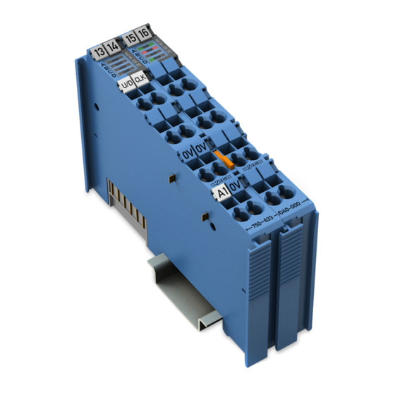
Device Description WAGO I/O SYSTEM 750 XTR 750-633/040-000 Up/Down Counter Ex i XTR View Figure 1: View Table 3: Legend for Figure “View” Pos. Description Details See Section Marking possibility with Mini- Status LEDs “Device Description” > “Display Elements” Data contacts “Device Description”... -
Page 17: Connectors
WAGO I/O SYSTEM 750 XTR Device Description 750-633/040-000 Up/Down Counter Ex i XTR Connectors 3.2.1 Data Contacts/Local Bus Communication between the fieldbus coupler/controller and the I/O modules as well as the system supply of the I/O modules is carried out via the local bus. The contacting for the local bus consists of 6 data contacts, which are available as self-cleaning gold spring contacts. -
Page 18: Power Jumper Contacts/Field Supply
The blade contacts are sharp-edged. Handle the I/O module carefully to prevent injury. Do not touch the blade contacts. The I/O module 750-633/040-000 has 2 self-cleaning power jumper contacts that supply and transmit power for the field side. The contacts on the left side of the I/O module are designed as blade contacts and those on the right side as spring contacts. -
Page 19: Cage Clamp ® Connectors
WAGO I/O SYSTEM 750 XTR Device Description 750-633/040-000 Up/Down Counter Ex i XTR 3.2.3 CAGE CLAMP ® Connectors Figure 4: CAGE CLAMP ® Connectors Table 5: Legend for Figure “CAGE CLAMP ® Connectors” Designation Connector Function In mode 1 and 3: Enable input Gate... -
Page 20: Display Elements
CLOCK Green Active signal at input CLOCK No error at input CLOCK or diagnostics not active Error CLOCK Error at input CLOCK: short circuit or wire break Operating Elements The I/O module 750-633/040-000 has no operating elements. Manual Version 1.1.0... -
Page 21: Schematic Diagram
WAGO I/O SYSTEM 750 XTR Device Description 750-633/040-000 Up/Down Counter Ex i XTR Schematic Diagram Figure 6: Schematic Diagram Manual Version 1.1.0... -
Page 22: Technical Data
Device Description WAGO I/O SYSTEM 750 XTR 750-633/040-000 Up/Down Counter Ex i XTR Technical Data 3.6.1 Device Data Table 7: Technical Data – Device Width 24 mm Height (from upper edge of DIN-rail) 60.6 mm Depth 100 mm Weight 88.2 g... -
Page 23: Inputs
WAGO I/O SYSTEM 750 XTR Device Description 750-633/040-000 Up/Down Counter Ex i XTR 3.6.4 Inputs Table 10: Technical Data – Inputs Number of inputs • U/D (Gate) • CLOCK Sensor supply U 8.2 VDC Signal current (0) ≤ 1.2 mA Signal current (1) ≥... -
Page 24: Explosion Protection, Inputs
Device Description WAGO I/O SYSTEM 750 XTR 750-633/040-000 Up/Down Counter Ex i XTR 3.6.7 Explosion Protection, Inputs Table 13: Technical Data – Explosion Protection, Inputs Power supply = 26.8 V via power jumper contacts = 2.2 W power consumption Interface circuit (system bus) -
Page 25: Explosion Protection, Output
WAGO I/O SYSTEM 750 XTR Device Description 750-633/040-000 Up/Down Counter Ex i XTR 3.6.8 Explosion Protection, Output Table 14: Technical Data – Explosion Protection, Output Power supply = 26.8 V via power jumper contacts = 2.2 W power consumption Interface circuit (system bus) -
Page 26: Connection Type
Device Description WAGO I/O SYSTEM 750 XTR 750-633/040-000 Up/Down Counter Ex i XTR 3.6.9 Connection Type Table 15: Technical Data – Field Wiring Wire connection CAGE CLAMP ® Cross section 0.25 mm² … 2.5 mm² / AWG 24 … 14 Stripped lengths 8 mm …... -
Page 27: Approvals
WAGO I/O SYSTEM 750 XTR Device Description 750-633/040-000 Up/Down Counter Ex i XTR Approvals The following approvals have been granted for the I/O module 750-633/040-000: Conformity marking UL61010-2-201 Korea Certification The following Ex approvals have been granted for the I/O module 750-633/040- 000: TÜV 17 ATEX 196484 X... - Page 28 PRS (Polski Rejestr Statków) More information about approvals. Detailed references to the approvals are listed in the document “Overview Approvals WAGO I/O SYSTEM 750”, which you can find via the internet under: www.wago.com DOWNLOADS Documentation System Description.
-
Page 29: Standards And Guidelines
WAGO I/O SYSTEM 750 XTR Device Description 750-633/040-000 Up/Down Counter Ex i XTR Standards and Guidelines 750-633/040-000 I/O modules meet the following standards and guidelines: Table 20: Standards and Rated Conditions for Explosion Protection Applications ATEX acc. Directive 2014/34/EU General Requirements... -
Page 30: Table 21: Climatic And Mechanical Environmental Conditions And Shipbuilding
Device Description WAGO I/O SYSTEM 750 XTR 750-633/040-000 Up/Down Counter Ex i XTR Table 21: Climatic and Mechanical Environmental Conditions and Shipbuilding Standard Test Value Transport EN 60870-2-2 Ct2(2k4) (except precipitation/water/moisture) Mechanical Environmental Conditions EN 61850-3 Achieved EN 60870-2-2 EN 60721-3-1... -
Page 31: Table 22: Emc - Immunity To Interference
WAGO I/O SYSTEM 750 XTR Device Description 750-633/040-000 Up/Down Counter Ex i XTR The I/O module 750-633/040-000 meets the following EMC standards as these standards relate to the I/O module: Table 22: EMC – Immunity to Interference Standard Test Value Electrostatic Discharge •... - Page 32 Device Description WAGO I/O SYSTEM 750 XTR 750-633/040-000 Up/Down Counter Ex i XTR Table 22: EMC – Immunity to Interference Standard Test Value Damped Oscillatory Waves • EN 61000-4-18 1.25 kV conductor/conductor • EN 60255-26 2.5 kV conductor/ground • IEEE C37.90.1...
-
Page 33: Table 23: Emc - Emission Of Interference
WAGO I/O SYSTEM 750 XTR Device Description 750-633/040-000 Up/Down Counter Ex i XTR Table 23: EMC – Emission of Interference Standard Test Value Enclosure Emission of Interference • EN 61000-6-3 30 dB(µV/m), QP, 30 MHz … 230 MHz • EN 55032 Class B 37 dB(µV/m), QP, 230 MHz …... - Page 34 Device Description WAGO I/O SYSTEM 750 XTR 750-633/040-000 Up/Down Counter Ex i XTR Table 23: EMC – Emission of Interference Standard Test Value Conducted Emission of Interference – Line Connection DC Voltage • EN 61000-6-3 79 dB(µV) QP, 0.15 MHz … 0.5 MHz •...
-
Page 35: Process Image
“I/O Modules” included in the description concerning the process image of the corresponding coupler/controller. The Up/Down Counter 750-633/040-000 provides 5 bytes of input and output process image to the fieldbus coupler/controller via 1 logical channel. -
Page 36: Set Counter
Process Image WAGO I/O SYSTEM 750 XTR 750-633/040-000 Up/Down Counter Ex i XTR Table 26: Status Byte S0, Operating Modes 1 and 2 Bit 7 Bit 6 Bit 5 Bit 4 Bit 3 Bit 2 Bit 1 Bit 0 NAMUR_... - Page 37 WAGO I/O SYSTEM 750 XTR Process Image 750-633/040-000 Up/Down Counter Ex i XTR Wait for feedback from the Up/Down Counter in the status byte, bit 5 (counter set). Status Byte S0 Input bit Bit 7 Bit 6 Bit 5 Bit 4...
-
Page 38: Operating Mode 3 - Frequency Counter
Process Image WAGO I/O SYSTEM 750 XTR 750-633/040-000 Up/Down Counter Ex i XTR Operating Mode 3 – Frequency Counter The Watchdog time to be set is stored in binary format in the 2 output bytes (D0, D1). The output bytes (D2, D3) are not used. In the 4 input bytes (D0 ... D3), the frequency value is stored in binary format. -
Page 39: Set Measuring Method, Frequency Range And Measured Value Display
WAGO I/O SYSTEM 750 XTR Process Image 750-633/040-000 Up/Down Counter Ex i XTR The following functions can be executed: 4.2.1 Set Measuring Method, Frequency Range and Measured Value Display The RANGE_SEL REQ bits in the control byte are used to set the measurement methods and display of the frequency value. -
Page 40: Set Watchdog Time
Process Image WAGO I/O SYSTEM 750 XTR 750-633/040-000 Up/Down Counter Ex i XTR 4.2.2 Set Watchdog Time To detect static CLOCK signals, a Watchdog time has been implemented. The default value for the time is 10 s. The time is reinitialized at each power-on. -
Page 41: Operating Mode 4 - Peak Time Counter
WAGO I/O SYSTEM 750 XTR Process Image 750-633/040-000 Up/Down Counter Ex i XTR Operating Mode 4 – Peak Time Counter In the 4 input bytes (D0 ... D3), the value of the counter is stored in binary format. Control byte C0 is used to start periodic counting and to set the outputs. Status byte S0 shows the counter status and the status of the inputs and outputs. -
Page 42: Set Output
Process Image WAGO I/O SYSTEM 750 XTR 750-633/040-000 Up/Down Counter Ex i XTR The following functions can be executed: 4.3.1 Set Output Bit 2 of the control byte sets the digital output DO. 4.3.2 Example The count direction is up (input U/D (Gate) = 24 V). The counter value is 0. - Page 43 WAGO I/O SYSTEM 750 XTR Process Image 750-633/040-000 Up/Down Counter Ex i XTR Status Byte S0 Input bit Bit 7 Bit 6 Bit 5 Bit 4 Bit 3 Bit 2 Bit 1 Bit 0 Value Cyclic recording is running. The counter value has been reset and the timer restarted.
-
Page 44: Mounting
750-633/040-000 Up/Down Counter Ex i XTR Mounting Mounting Sequence Fieldbus couplers, controllers and I/O modules of the WAGO I/O SYSTEM 750 are snapped directly on a carrier rail in accordance with the European standard EN 60175 (DIN 35). The reliable positioning and connection is made using a tongue and groove system. - Page 45 Always plug a bus end module 750-600/040-000 onto the end of the fieldbus node! You must always use this bus end module at all fieldbus nodes with the WAGO I/O SYSTEM 750 XTR fieldbus couplers/controllers to guarantee proper data transfer.
-
Page 46: Inserting And Removing Devices
Mounting WAGO I/O SYSTEM 750 XTR 750-633/040-000 Up/Down Counter Ex i XTR Inserting and Removing Devices Do not touch hot surfaces! The surface of the housing can become hot during operation. If the device was operated at high ambient temperatures, allow it to cool off before touching it. -
Page 47: Removing The I/O Module
WAGO I/O SYSTEM 750 XTR Mounting 750-633/040-000 Up/Down Counter Ex i XTR Press the I/O module into the assembly until the I/O module snaps into the carrier rail. Figure 8: Snap the I/O Module into Place (Example) With the I/O module snapped in place, the electrical connections for the data contacts and power jumper contacts (if any) to the fieldbus coupler/controller or to the previous or possibly subsequent I/O module are established. -
Page 48: Connect Devices
Do not connect more than one conductor at one single connection! If more than one conductor must be routed to one connection, these must be connected in an up-circuit wiring assembly, for example using WAGO feed- through terminals. For opening the CAGE CLAMP insert the actuating tool into the opening ®... -
Page 49: Power Supply Concept
Further information about explosion prevention can be found in section “Use in Hazardous Environments”! The Ex i XTR I/O module (750-633/040-000) receives the 24 V voltage supply potential and the 0V potential for the field level from an upstream Ex i XTR I/O module or from the “Power Supply 24 VDC Diagn for Ex i XTR Modules”... -
Page 50: Figure 11: Ex I Xtr Power Supply Concept
750-633/040-000 Up/Down Counter Ex i XTR 606/040-000 via the power contacts designed as blade contacts. The Ex i XTR I/O module (750-633/040-000) provides these potentials to subsequent I/O modules via the power contacts designed as spring contacts. Figure 11: Ex i XTR Power Supply Concept Table 34: Legend for Figure “Ex i XTR Power Supply Concept”... -
Page 51: Figure 12: Overvoltage Categories
WAGO I/O SYSTEM 750 XTR Connect Devices 750-633/040-000 Up/Down Counter Ex i XTR Figure 12: Overvoltage Categories Table 35: Legend for Figure “Overvoltage Categories” Pos. Explanation XTR fieldbus coupler/controller XTR filter module XTR supply module “Power Supply 24 VDC Diagn for Ex i XTR Modules”... -
Page 52: Supplementary Power Supply Regulations
6.2.1 Supplementary Power Supply Regulations The WAGO I/O SYSTEM 750 XTR can also be used in shipbuilding applications and onshore/offshore installations (e.g., platforms, loading facilities), as well as in telecontrol applications. This is possible via certification under the standards of leading agencies such as DNV GL and Lloyds Register. -
Page 53: Figure 13: Power Supply Concept, Example 1
WAGO I/O SYSTEM 750 XTR Connect Devices 750-633/040-000 Up/Down Counter Ex i XTR Figure 13: Power Supply Concept, Example 1 Table 37: Legend for Figure “Power Supply Concept, Example 1” Pos. Explanation XTR fieldbus coupler / controller XTR filter module 750-626/040-000 XTR supply “Power Supply 24 VDC Diagn for Ex i XTR Modules”... -
Page 54: Figure 14: Power Supply Concept, Example 2
Connect Devices WAGO I/O SYSTEM 750 XTR 750-633/040-000 Up/Down Counter Ex i XTR Figure 14: Power Supply Concept, Example 2 Table 38: Legend for Figure “Power Supply Concept, Example 2“ Pos. Explanation XTR fieldbus coupler / controller XTR filter module 750-626/040-000 XTR filter module (750-626/040-000 or 750-624/040-001) XTR supply 750-606/040-000 “Power Supply 24 VDC Diagn for Ex i XTR... -
Page 55: Connection Example
WAGO I/O SYSTEM 750 XTR Connect Devices 750-633/040-000 Up/Down Counter Ex i XTR Connection Example Figure 15: Connection Example Use shielded signal lines! Only use shielded signal lines for CLOCK and U/D (Gate) inputs. Only then can you ensure that the specified accuracy and interference immunity can be achieved even in the presence of interference acting on the signal cable. -
Page 56: Parameterizing
Parameterizing WAGO I/O SYSTEM 750 XTR 750-633/040-000 Up/Down Counter Ex i XTR Parameterizing Parameterization with WAGO-I/O-CHECK 7.1.1 Parameter Dialog Box Figure 16: Parameter Dialog Box (Example) The parameter dialog box is divided into the following areas: • Titlebar with position and item number of the selected I/O module, •... -
Page 57: Toolbar
Reads out the current settings from the attached Read device. Transfers the indicated settings into the attached Write device. Resets the selected I/O module to the WAGO Default default values. Shows the help WAGO-I/O-CHECK. Help Manual Version 1.1.0... -
Page 58: Parameter
7.1.1.2 Parameter Figure 18: Parameter Following select boxes are shown in the dialog box: Table 40: Up/Down Counter Ex i XTR (750-633/040-000) – Parameter Select box Available settings Counting Mode Up Counter with With a positive edge on the CLOCK input,... -
Page 59: Use In Hazardous Environments
Use in Hazardous Environments 750-633/040-000 Up/Down Counter Ex i XTR Use in Hazardous Environments The WAGO I/O SYSTEM 750 (electrical equipment) is designed for use in Zone 2 hazardous areas and shall be used in accordance with the marking and installation regulations. -
Page 60: Marking Configuration Examples
Use in Hazardous Environments WAGO I/O SYSTEM 750 XTR 750-633/040-000 Up/Down Counter Ex i XTR Marking Configuration Examples 8.1.1 Marking for Europe According to ATEX and IECEx Figure 19: Marking Example According to ATEX and IECEx Figure 20: Text Detail – Marking Example According to ATEX and IECEx Manual Version 1.1.0... -
Page 61: Table 41: Description Of Marking Example According To Atex And Iecex
WAGO I/O SYSTEM 750 XTR Use in Hazardous Environments 750-633/040-000 Up/Down Counter Ex i XTR Table 41: Description of Marking Example According to ATEX and IECEx Marking Description TUEV 07 ATEX 554086 X Approving authority resp. certificate numbers IECEx TUN 09.0001 X... -
Page 62: Figure 21: Marking Example For Approved Ex I I/O Module According To
Use in Hazardous Environments WAGO I/O SYSTEM 750 XTR 750-633/040-000 Up/Down Counter Ex i XTR Figure 21: Marking Example for Approved Ex i I/O Module According to ATEX and IECEx Figure 22: Text Detail – Marking Example for Approved Ex i I/O Module According to ATEX and... -
Page 63: Table 42: Description Of Marking Example For Approved Ex I I/O Module According To Atex And Iecex
WAGO I/O SYSTEM 750 XTR Use in Hazardous Environments 750-633/040-000 Up/Down Counter Ex i XTR Table 42: Description of Marking Example for Approved Ex i I/O Module According to ATEX and IECEx Marking Description TUEV 12 ATEX 106032 X Approving authority resp. certificate numbers... -
Page 64: Marking For The United States Of America (Nec) And Canada (Cec)
Use in Hazardous Environments WAGO I/O SYSTEM 750 XTR 750-633/040-000 Up/Down Counter Ex i XTR 8.1.2 Marking for the United States of America (NEC) and Canada (CEC) Figure 23: Marking Example According to NEC Figure 24: Text Detail – Marking Example According to NEC 500... -
Page 65: Figure 25: Text Detail - Marking Example For Approved Ex I I/O Module
WAGO I/O SYSTEM 750 XTR Use in Hazardous Environments 750-633/040-000 Up/Down Counter Ex i XTR Figure 25: Text Detail – Marking Example for Approved Ex i I/O Module According to NEC 505 Table 44: Description of Marking Example for Approved Ex i I/O Module According to NEC 505... -
Page 66: Figure 27: Text Detail - Marking Example For Approved Ex I I/O Modules
Use in Hazardous Environments WAGO I/O SYSTEM 750 XTR 750-633/040-000 Up/Down Counter Ex i XTR Figure 27: Text Detail – Marking Example for Approved Ex i I/O Modules According to CEC 18 attachment J Table 46: Description of Marking Example for Approved Ex i I/O Modules According to CEC 18... -
Page 67: Installation Regulations
WAGO I/O SYSTEM 750 XTR Use in Hazardous Environments 750-633/040-000 Up/Down Counter Ex i XTR Installation Regulations For the installation and operation of electrical equipment in hazardous areas, the valid national and international rules and regulations which are applicable at the installation location must be carefully followed. - Page 68 Use in Hazardous Environments WAGO I/O SYSTEM 750 XTR 750-633/040-000 Up/Down Counter Ex i XTR Explosive atmosphere occurring simultaneously with assembly, installation or repair work must be ruled out. Among other things, these include the following activities • Insertion and removal of components •...
-
Page 69: Special Notes Regarding Ansi/Isa Ex
WAGO I/O SYSTEM 750 XTR Use in Hazardous Environments 750-633/040-000 Up/Down Counter Ex i XTR 8.2.2 Special Notes Regarding ANSI/ISA Ex For ANSI/ISA Ex acc. to UL File E198726, the following additional requirements apply: • Use in Class I, Division 2, Group A, B, C, D or non-hazardous areas only •... -
Page 70: List Of Figures
List of Figures WAGO I/O SYSTEM 750 XTR 750-633/040-000 Up/Down Counter Ex i XTR List of Figures Figure 1: View ...................... 16 Figure 2: Data Contacts ..................17 Figure 3: Power Jumper Contacts ............... 18 Figure 4: CAGE CLAMP Connectors ..............19 ®... -
Page 71: List Of Tables
Table 38: Legend for Figure “Power Supply Concept, Example 2“ ..... 54 Table 39: Legend for Figure “Toolbar“ ..............57 Table 40: Up/Down Counter Ex i XTR (750-633/040-000) – Parameter .... 58 Table 41: Description of Marking Example According to ATEX and IECEx..61 Table 42: Description of Marking Example for Approved Ex i I/O Module According to ATEX and IECEx .............. - Page 72 List of Tables WAGO I/O SYSTEM 750 XTR 750-633/040-000 Up/Down Counter Ex i XTR Table 44: Description of Marking Example for Approved Ex i I/O Module According to NEC 505 ................65 Table 45: Description of Marking Example for Approved Ex i I/O Modules According to NEC 506 ................
- Page 73 WAGO I/O SYSTEM 750 XTR 750-633/040-000 Up/Down Counter Ex i XTR Manual Version 1.1.0...
- Page 74 WAGO Kontakttechnik GmbH & Co. KG Postfach 2880 • D - 32385 Minden Hansastraße 27 • D - 32423 Minden Phone: +49 571 887 – 0 Fax: +49 571 887 – 844169 E-Mail: info@wago.com Internet: www.wago.com...
Need help?
Do you have a question about the 750-633/040-000 and is the answer not in the manual?
Questions and answers