Table of Contents
Advertisement
Quick Links
Modem-converter E1-L
User's Guide
1 2 3 4 5 6 7 8 9 0 1 2 3 4 5 6 7 8 9 0 1 2 3 4 5 6 7 8 9 0 1 2 1 2 3 4 5 6 7 8 9 0 1 2 3 4 5 6 7 8 9 0 1 2 3 4 5 6 7 8 9 0 1 2 1 2 3 4 5 6 7 8 9 0 1 2 3 4 5 6 7 8 9 0 1 2 3 4 5 6 7 8 9 0 1 2 1 2 3 4 5 6 7
1 2 3 4 5 6 7 8 9 0 1 2 3 4 5 6 7 8 9 0 1 2 3 4 5 6 7 8 9 0 1 2 1 2 3 4 5 6 7 8 9 0 1 2 3 4 5 6 7 8 9 0 1 2 3 4 5 6 7 8 9 0 1 2 1 2 3 4 5 6 7 8 9 0 1 2 3 4 5 6 7 8 9 0 1 2 3 4 5 6 7 8 9 0 1 2 1 2 3 4 5 6 7
Features
• E1 G703/G704 channel
• Distance up to 1.5 km
• V.35/RS-530/RS-449/RS-232/X.21/
Ethernet user data interface
• Data rate from 64 kbps up to 2048
kbps
• Programmable timeslot assignment
• G.703 2048 kbps unframed mode
• Cronyx PCM2 compatibility
• CAS and CRC4 framing
• Synchronization from digital inter-
face (DTE emulation)
• Digital, local and remote loopbacks
• Integrated BER tester
• RS-232 Control port
• Dry contacts alarm interface
• Stand-alone or rack-mount (19''3U)
• AC or DC power
Copyright © 1998-2000 Cronyx
Modem E1
Contents
Transmit Clock Inversion
1
1.0E / 01.12.2000
Advertisement
Table of Contents

Related Manuals for Cronyx E1-L

Summary of Contents for Cronyx E1-L
-
Page 1: Table Of Contents
Controls on Front Panel • Programmable timeslot assignment Front Panel Indicators DIP Switches • G.703 2048 kbps unframed mode Jumpers • Cronyx PCM2 compatibility Line Impedance Transmit Clock Inversion • CAS and CRC4 framing Clock Source Selection • Synchronization from digital inter-... -
Page 2: Description
G.704 recommendation). E1-L device is available as stand-alone unit Modem E1-L is also available as a card for or as a card for 19’’ 3U Cronyx rack. Rack Intel-compatible computers (Cronyx-Tau/ mount modem consists of two cards one E1, Cronyx Tau-PCI/E1). -
Page 3: Specifications
Diagnostics Loopbacks .......... Digital, local (G.703 line on local unit), remote (G.703 line on remote unit), selected by front panel switches or via control port BER Tester.......... Activated by front panel switch or via control port Copyright © 1998-2000 Cronyx... -
Page 4: Ordering Code
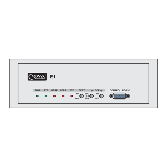
LOOP1 LOOP2 B – stand-alone unit Disable R – Rack mount card Model: Local loop on link E1 E1-L – modem E1 Remote loop on link E1 Digital loop Front panel indicators Indicator Description Power supply Digital interface signal (Ready to... -
Page 5: Dip Switches
S1 group — E1 frame timeslots or data transfer rate on digital port in unframed operation mode. S3 group — Modem configuration & syn- chronization. Copyright © 1998-2000 Cronyx... - Page 6 As a result of this delay errors can occur at some data rates. The problem can be solved Copyright © 1998-2000 Cronyx...
- Page 7 Unframed Mode Selection S1-1...S1-5 - initial timeslot of E1 frame timeslot 1 (one, not zero) S3-8 switch controls unframed mode se- timeslot 1 lection. In this mode E1-L modem is com- timeslot 2 patible with Cronyx PCM2. timeslot 3 timeslot 4...
-
Page 8: Jumpers
27 timeslots — 1728 kbps E1 line impedance 28 timeslots — 1792 kbps jumpers 29 timeslots — 1856 kbps 30 timeslots — 1920 kbps 31 timeslots — 1984 kbps, 2048 kbps in unframed mode Rack-mount card Copyright © 1998-2000 Cronyx... -
Page 9: Clock Source Selection
Example of the source, i.e. Int – RCV or EXT – RCV. Indi- mode is shown in figure on the next page. cation signal corresponds to CD signal and Control signal – to RTS signal. Copyright © 1998-2000 Cronyx... -
Page 10: Loop Selection
LOOP1 switch is ON, LOOP2 switch is DIG. Local Remote modem, modem, local normal loopback operation Local Remote modem, modem, digital normal loopback operation Carrier Carrier "OFF" "ON" "ON" S3/4 S3/4 Carrier S3/5 S3/5 "ON" "ON" S3/4 S3/4 S3/5 S3/5 Copyright © 1998-2000 Cronyx... -
Page 11: Alarm Interface
Normal connected mode can be set through console. In this case input contacts should be connected by sensor. If input contacts are disconnected remote unit is set to “alarm” state. Copyright © 1998-2000 Cronyx... -
Page 12: Rear Panel Connectors
— Âõîä RC-a Ouput DTR-a Âõîä RC-b Ouput DTR-b — Âõîä Input DSR-a Âûõîä Input DSR-b — Âûõîä Ouput CTS-a Âûõîä Ouput CTS-b — Âûõîä Ouput CD-a Âûõîä CGND — CD-b — Âûõîä SGND — — Copyright © 1998-2000 Cronyx... -
Page 13: Console
• input alarm sensor mode; • RXC inversion; ERC-b ERC-b — — • compatibility mode. RTS-a RTS Control(A) — RTS-b — Control(B) Console connector has standard DTE wir- DTR-a DTR — ing: — DTR-b — — DSR-a DSR — Copyright © 1998-2000 Cronyx... - Page 14 1 3 5 7 9 1 3 5 7 9 1 3 5 7 9 1 Timeslots 0: ###############....Timeslots 1: ....############### 1. Configure... 2. Statistics 3. Loopback... 4. Link test - stopped 0. Reset Command: _ Copyright © 1998-2000 Cronyx...
- Page 15 Loss of frame on remote modem AIS16 Timeslot 16 alarm indicator signal FARLOMF Loss of multiframe on remote modem CRCE Checksum error RCRCE Checksum error on remote modem «Loopback» menu controls local, digital and remote loopbacks: Copyright © 1998-2000 Cronyx...
-
Page 16: Cables Wiring
TXD-b RXD-b V.35 DCE cable wiring for –M models with external transmit RXD-a TXD-a clock (DTE1 emulation mode) RXD-b TXD-b ETC-a RXC-a Signal HDB44 (male) M34 (male) ETC-b RXC-b TXD-a RXD-a RXC-a Not connected TXD-b RXD-b Copyright © 1998-2000 Cronyx... - Page 17 M34 (male) TXC-b TXD-a RXD-a RXC-a TXD-b RXD-b RXC-b RXD-a TXD-a ERC-a RXD-b TXD-b ERC-b ETC-a RXC-a ETC-b RXC-b RXC-a Not connected RXC-b Not connected SEL-x 31,39,41,43 TXC-a Not connected connect to GND 1 TXC-b Not connected Copyright © 1998-2000 Cronyx...
- Page 18 RS-530 cable wiring for –M models Signal HDB44 (male) DB37 (female) TXD-a Signal HDB44 (male) DB25 (female) TXD-b TXD-a RXD-a TXD-b RXD-b RXD-a ETC-a RXD-b ETC-b ETC-a TXC-a ETC-b TXC-b TXC-a RXC-a TXC-b RXC-b RXC-a ERC-a RXC-b ERC-b Copyright © 1998-2000 Cronyx...
- Page 19 Signal HDB44 (male) HDB44 (male) Signal TXC-b TXD-a RXD-a RTS-a TXD-b RXD-b RTS-b RXD-a TXD-a CD-a RXD-b TXD-b CD-b ETC-a RXC-a ETC-b RXC-b RXC-a ETC-a SEL-x 33,37 RXC-b ETC-b connect to GND 16 TXC-a Not connected Copyright © 1998-2000 Cronyx...
- Page 20 E1-L ODEM 1 2 3 4 5 6 7 8 9 0 1 2 3 4 5 6 7 8 9 0 1 2 3 4 5 6 7 8 9 0 1 2 1 2 3 4 5 6 7 8 9 0 1 2 3 4 5 6 7 8 9 0 1 2 3 4 5 6 7 8 9 0 1 2 1 2 3 4 5 6 7 8 9 0 1 2 3 4 5 6 7 8 9 0 1 2 3 4 5 6 7 8 9 0 1 2 1 2 3 4 5 6 7 8 9 0 1 2 3 4 5 6 7 8 9 0 1 2 3 4 5 6 7 8 9 0 1 2 1 2 3 4 5 6 7 8 9...
Need help?
Do you have a question about the E1-L and is the answer not in the manual?
Questions and answers