Table of Contents
Advertisement
Quick Links
Advertisement
Table of Contents

Related Manuals for Unipower Quick-Set PowerCassette PCHS Series

Summary of Contents for Unipower Quick-Set PowerCassette PCHS Series
- Page 1 Artisan Technology Group is your source for quality new and certified-used/pre-owned equipment SERVICE CENTER REPAIRS WE BUY USED EQUIPMENT • FAST SHIPPING AND DELIVERY Experienced engineers and technicians on staff Sell your excess, underutilized, and idle used equipment at our full-service, in-house repair center We also offer credit for buy-backs and trade-ins •...
- Page 2 ® ADVANCED MULTI-OUTPUT SWITCHER AND RACKS www.unipowerco.com © 2014 UNIPOWER LLC Manual No. TPCHS-2 All Rights Reserved pchs-tpchs-man-rev2-1214.indd NORTH AMERICA • 3900 Coral Ridge Drive, Coral Springs, Florida 33065, USA • Tel: +1 954-346-2442 • Fax: +1 954-340-7901 • sales-northamerica@unipowerco.com EUROPE •...
-
Page 3: Table Of Contents
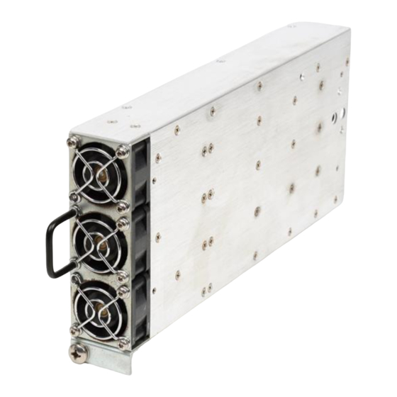
PCHS/TPCHS SERIES Quick-Set PowerCassette® INSTALLATION & OPERATING MANUAL Contents INTRODUCTION ........................ 4 QUICK-SET POWERCASSETTE FEATURES ..............5 SUMMARY OF PRODUCT LINE ..................6 SAFETY WARNINGS ......................6 WARRANTY (summary) ..................... 7 UNPACKING AND INSPECTION ..................7 DESCRIPTION OF OPERATION..................7 FRONT PANEL DESCRIPTION .................. - Page 4 PCHS/TPCHS SERIES Quick-Set PowerCassette® INSTALLATION & OPERATING MANUAL FIGURES Figure 1 - Quick-Set PowerCassette Models (hot-swap model shown) ..........4 Figure 2 - PowerCassette Simplified Block Diagram (AC Input) ...........5 Figure 3 - Front Panel of the Quick-Set PowerCassette ..............8 Figure 4 - Mechanical Dimensions of PowerCassette ..............11 Figure 5 - Connectors and Pin Connections to PowerCassette ............12 Figure 6 - Output Voltage Adjustment (V1 &...
-
Page 5: Introduction
PCHS/TPCHS SERIES Quick-Set PowerCassette® INSTALLATION & OPERATING MANUAL OPERATING MANUAL PCHS/TPCHS QUICK-SET PowerCassette ® ADVANCED, MULTI-OUTPUT SWITCHER INTRODUCTION This operating manual should be read through carefully before installing and operating the PCHS/ TPCHS Quick-Set PowerCassette®. The Quick-Set PowerCassette is an advanced-design, multi-output switching power supply that employs a unique, new cellular architecture which permits quick factory programming of its outputs by means of internal DIP switches to meet virtually any requirement. -
Page 6: Quick-Set Powercassette Features
PCHS/TPCHS SERIES Quick-Set PowerCassette® INSTALLATION & OPERATING MANUAL Figure 2 - PowerCassette Simplified Block Diagram (AC Input) QUICK-SET POWERCASSETTE FEATURES The following is a summary of the important features of the Quick-Set PowerCassette Outputs Set by Internal DIP Switches ... -
Page 7: Summary Of Product Line
PCHS/TPCHS SERIES Quick-Set PowerCassette® INSTALLATION & OPERATING MANUAL SUMMARY OF PRODUCT LINE The Quick-Set PowerCassette product line consists of 254 AC input models and 254 DC input models, or 508 different models total. There is a choice of five outputs plus a 5V, 250 mA standby output, giving a total of up to six outputs. -
Page 8: Warranty (Summary)
God, negligence or the failure of customer to fully follow instructions with respect to installation, application or maintenance. For a complete text of UNIPOWER’s warranty conditions please request a copy from your local Sales Office. -
Page 9: Front Panel Description
PCHS/TPCHS SERIES Quick-Set PowerCassette® INSTALLATION & OPERATING MANUAL FRONT PANEL DESCRIPTION The front panel of the Quick-Set PowerCassette is shown in Figure 3. On the left bottom of the panel is the Input Power Good LED (green) and on the right bottom is the Output Power Good LED (green). -
Page 10: Description Of Features & Options
PCHS/TPCHS SERIES Quick-Set PowerCassette® INSTALLATION & OPERATING MANUAL 10.0 DESCRIPTION OF FEATURES & OPTIONS FEATURE / OPTION DESCRIPTION Power Factor Correction The input current is a sine wave in-phase with the input voltage to give a power factor of 0.99. Input current total harmonic distortion meets EN61000-3-2. - Page 11 PCHS/TPCHS SERIES Quick-Set PowerCassette® INSTALLATION & OPERATING MANUAL FEATURE / OPTION DESCRIPTION No Load Operation All PowerCassette outputs can be operated down to zero load while maintaining output regulation. Hot-Swap Connectors The hot-swap connectors used in both the PowerCassette and rack are specifically designed for hot-swap applications.
-
Page 12: Mechanical Specifications
PCHS/TPCHS SERIES Quick-Set PowerCassette® INSTALLATION & OPERATING MANUAL 11.0 MECHANICAL SPECIFICATIONS The mechanical dimensions of the Quick-Set PowerCassette are shown in Figure 4. Figure 4 - Mechanical Dimensions of PowerCassette 12.0 SAFETY AND INDUSTRY STANDARDS The Quick-Set PowerCassette meets the following safety certifications: 12.1 STANDARD AGENCY UL1950... -
Page 13: Operating Information
PCHS/TPCHS SERIES Quick-Set PowerCassette® INSTALLATION & OPERATING MANUAL 13.0 OPERATING INFORMATION 13.1 Input Voltage and Connection. The AC version of the PowerCassette operates off worldwide AC input voltages in the range of 85 to 264 VAC at 47 to 63 Hz. The three-wire AC connection is made to pins 45-47 on the large Positronics connector. -
Page 14: Figure 6 - Output Voltage Adjustment (V1 & V2)
PCHS/TPCHS SERIES Quick-Set PowerCassette® INSTALLATION & OPERATING MANUAL 13.3 Output Voltages. Each output voltage is factory set to its nominal value to an accuracy of ±1%. The V1 and V2 output voltages can be more accurately adjusted to a value within a ±5% range by means of external components as shown in Figure 6. -
Page 15: Figure 8 - Remote Sensing Connection For Each V1, V2 Or V3 Output
PCHS/TPCHS SERIES Quick-Set PowerCassette® INSTALLATION & OPERATING MANUAL 13.6 Remote Sensing. Remote sensing connections for V1, V2 and V3 are made to the desig- nated pins on the large Positronics connector. Remote sensing is not available on the low current V4 and V5 outputs or on the Standby +5V, 250 mA output. Remote sensing is used to regulate the output voltage at the point of load by compensating for the voltage drop in the wires to the load. -
Page 16: Parallel Operation
PCHS/TPCHS SERIES Quick-Set PowerCassette® INSTALLATION & OPERATING MANUAL 13.10 I²C Option. This option provides an industry standard I²C serial data bus interface which provides the status of system-critical operating parameters. This permits the montoring of these parameters on demand by a host system or computer. Three forms of data are available from the PowerCassette by means of its I²C capability: inventory control information, operating status indication and system load data. -
Page 17: Compatible 19-Inch Racks
PCHS/TPCHS SERIES Quick-Set PowerCassette® INSTALLATION & OPERATING MANUAL 15.0 COMPATIBLE 19-INCH RACKS Figure 9 shows the two 19-inch compatible racks holding two or three PowerCassette units 15.1 These racks have the following features: • Standard 19-Inch Rack-Mounting • Only 1U High •... - Page 18 PCHS/TPCHS SERIES Quick-Set PowerCassette® INSTALLATION & OPERATING MANUAL 15.2 Two-Unit Rack. The two-unit, 19-inch rack is shown in Figure 10 with connections and pin designations. There is a choice of single or dual IEC60320 AC input connectors or single or dual terminal block AC or DC input connectors. The various connector versions are summarized in the following table.
-
Page 19: Figure 10 - Two-Unit Rack With Connections
PCHS/TPCHS SERIES Quick-Set PowerCassette® INSTALLATION & OPERATING MANUAL 15.2.8 For details on control signals, see Section 16 and Figure 10. FRONT VIEW BACK VIEW V1 & V2 Connections are to No. ¼ - 20 bolts P2 PIN CONNECTIONS P1 PIN CONNECTIONS PIN FUNCTION PIN FUNCTION PIN FUNCTION... - Page 20 PCHS/TPCHS SERIES Quick-Set PowerCassette® INSTALLATION & OPERATING MANUAL 15.3 Three-Unit Rack. The three-unit, 19-inch rack is shown in Figure 11 with connections and pin designations. For AC input there is a choice of an IEC60320 or a terminal block connector. The connector comes only on the rear panel. For information on the DC input connector, contact the factory.
-
Page 21: Figure 11 - Three-Unit Rack With Connections
PCHS/TPCHS SERIES Quick-Set PowerCassette® INSTALLATION & OPERATING MANUAL V1 & V2 Connections are to No. ¼ - 20 bolts P2 PIN CONNECTIONS P1 PIN CONNECTIONS PIN FUNCTION PIN FUNCTION PIN FUNCTION PIN FUNCTION Output Good/ Data-A Input Power Fail-A V3 Common V4 Out +5V Standby-A Inhibit-A... -
Page 22: Description Of Control And Supervisory Signals
PCHS/TPCHS SERIES Quick-Set PowerCassette® INSTALLATION & OPERATING MANUAL 16.0 DESCRIPTION OF CONTROL AND SUPERVISORY SIGNALS The pin numbers shown below refer to the Positronics connector on the PCHS or TPCHS unit. For the corresponding rack pin numbers, see Section 15 and Figures 10 and 11. SIGNAL PINS DESCRIPTION... -
Page 23: Installation
PCHS/TPCHS SERIES Quick-Set PowerCassette® INSTALLATION & OPERATING MANUAL SIGNAL PINS DESCRIPTION A logic LO at this output indicates an overtemperature condition inside the unit. The LO occurs a few milliseconds before the unit Overtemperature shuts down. The equivalent circuit is an NPN transistor collector Warning with a 10k ohm resistor to +5V. -
Page 24: Maintenance
PCHS/TPCHS SERIES Quick-Set PowerCassette® INSTALLATION & OPERATING MANUAL 17.6 Control and Supervisory Signal Connections. These connections are made to various pins on the large Positronic connector on the PowerCassette. See Figure 5. For the racks they are made to various pins on the P2 connector. See Figures 10 and 11. Details for these functions are given in Section 16. - Page 25 PCHS/TPCHS SERIES Quick-Set PowerCassette® INSTALLATION & OPERATING MANUAL PowerCassette, to Signal Ground, pin 22. This must be done for the unit to operate. When using the rack, the Enable pin is automatically connected to Signal Ground in the rack. The units are then controlled by the Inhibit inputs, P2 pins 1 and 13 of the two-unit rack or pins 15, 20 and 24 of the three-unit rack.
-
Page 26: Troubleshooting Guide
UK +44 (0)1903 768200 IX SELECTOR This document is believed to be correct at time of publication and UNIPOWER LLC accepts no responsibility for consequences from printing errors or inaccuracies. Specifications are subject to change without notice. Manual No. tpchs-2 pchs-tpchs-man-rev2-1214.indd... - Page 27 PCHS/TPCHS SERIES Quick-Set PowerCassette® INSTALLATION & OPERATING MANUAL APPENDIX 1 QUICK-SET PowerCassette® MODEL SUFFIX SELECTOR MODEL MODEL SUFFIX SUFFIX FCOOE 12V/35A 2.5V/50A -12V/3A -5V/3A FBOGE 12V/35A 3.3V/50A -5V/3A 12V/35A 2.5V/50A -12V/3A 5V/3A FBOGD 12V/35A 3.3V/50A -12V/3A -5.2V/3A FCOGK -5V/3A FBOOE 3.3V/50A 5V/10A 1.8V/3A...
- Page 28 PCHS/TPCHS SERIES Quick-Set PowerCassette® INSTALLATION & OPERATING MANUAL QUICK-SET PowerCassette® MODEL SUFFIX SELECTOR (CONTINUED) MODEL MODEL SUFFIX SUFFIX -12V/3A -5V/3A ADFGE 2.5V/70A -12V/3A -5V/3A BOOGE 1.8V/70A 5V/50A 12/10A 2.5V/70A 12V/3A 3.3V/3A BOOFC 1.8V/70A 5V/50A 12/10A -12V/3A ADFGO -12V/3A 5V/3A BOOGD 5V/50A 12/10A -5V/3A...
- Page 29 PCHS/TPCHS SERIES Quick-Set PowerCassette® INSTALLATION & OPERATING MANUAL APPENDIX 2 : I²C SERIAL BUS INTERFACE ® PowerCassette Status Indication of system critical power supply parameters DESCRIPTION The I²C interface that is incorporated into the PowerCassette includes facilities to monitor various operating parameters within the unit and transmit these to a host computer on demand over an industry standard I²C Serial bus.
- Page 30 PCHS/TPCHS SERIES Quick-Set PowerCassette® INSTALLATION & OPERATING MANUAL OPERATION AND FUNCTIONS Digital Functions Analogue Functions Digital status functions are provided by a PCF8574 8-bit Analogue status functions are provided by two PCF8591 I/O port device. When this device is read by the serial 4-channel 8-bit A/D converter devices.
- Page 31 Power is applied. This is already connected on the the loads be connected such that the different outputs UNIPOWER PCB Interface Board but will need to are returned to separate returns at the power supply. be connected if using a wired mating connector. If...
- Page 32 Artisan Technology Group is your source for quality new and certified-used/pre-owned equipment SERVICE CENTER REPAIRS WE BUY USED EQUIPMENT • FAST SHIPPING AND DELIVERY Experienced engineers and technicians on staff Sell your excess, underutilized, and idle used equipment at our full-service, in-house repair center We also offer credit for buy-backs and trade-ins •...
Need help?
Do you have a question about the Quick-Set PowerCassette PCHS Series and is the answer not in the manual?
Questions and answers